
Installation and Operation Guide
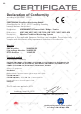
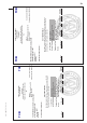
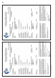
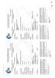
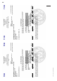
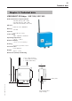
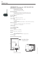
Table Of Contents
- Chapter 1: Introduction
- 1.1 First steps
- 1.2 Service addresses
- 1.3 About this manual
- Chapter 2: Safety
- 2.1 Safety symbols
- 2.2 Information for the system operator
- 2.3 Information for operating personnel
- 2.4 Intended use
- 2.5 Residual risks and safety measures
- Declaration of conformity
- Certifications
- Chapter 3: Technical data
- Chapter 4: System description
- 4.1 VIBCONNECT RF bridge
- 4.2 VIBCONNECT RF sensor unit
- 4.3 VIBCONNECT RF sensor
- Chapter 5: Installation & commissioning
- 5.1 Quick guide
- 5.2 Configuration in OMNITREND
- 5.3 Installation & commissioning of bridge
- 5.4 Installation & commissioning of sensor unit
- 5.5 Installation of sensors
- 5.6 Configuration in OMNITREND (continued)
- 5.7 Installing additional sensor unit
- Chapter 6: Maintenance
- 6.1 Cleaning
- 6.2 System time correction
- 6.3 Installation report
- 6.4 Battery-powered sensor unit
- 6.5 Update
- 6.6 Warranty
- 6.7 Spare parts and accessories
- Chapter 7: Troubleshooting
- Chapter 8: After use

17
VIBCONNECT RF 05.2012
Chapter 3: Technical data
VIBCONNECT RF Bridge – VIB 7.220, VIB 7.225
Radio transmission frequency band
868 MHz (Europe, VIB 7.220)
916 MHz (America, VIB 7.220)
2435 MHz (Worldwide, VIB 7.225)
Ethernet
Baud rate: 10 / 100 Mbit/s
Memory
256 MB
Capacity
up to 50 sensor units
Power supply
100 ... 240 VAC / 50-60 Hz
Operating temperature
– 25 °C ... +60 °C
Relative humidity
< 95 %, non-condensing
Housing
Steel sheet, powder-coated
Protection class
IP 66, NEMA 4
Weight
approx. 1.8 kg
Dimensions (in mm) and labeling
Technical data
Name plate
Power supply label
(High voltage)
150
R8
110
170
176
211
333
95
Color coding, antenna:
• Grey (868 / 915 MHz)
• Purple (2435 MHz)