(Undefined variable: General.
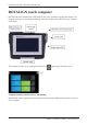
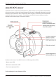
(Undefined variable: General.UserGuideTitle) ROTALIGN touch computer ROTALIGN touch computer has a multi-touch screen and is operated by tapping and swiping. The computer is turned on by pressing and holding down the On/Off switch at the front of the computer until it beeps. The computer is turned off by tapping the On/Off icon [ ] appearing in the home screen.
(Undefined variable: General.UserGuideTitle) ROTALIGN touch computer has a built-in camera at the back of the unit which may be used to capture machine images.
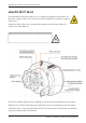
(Undefined variable: General.UserGuideTitle) sensALIGN laser The semiconductor laser diode emits a ray of red light (wavelength 635 nm) which is visible where it strikes a surface. The Class 2 laser beam is emitted with a diameter of approx. 5 mm (3/16”). sensALIGN laser is turned on by pressing and holding the On/Off switch briefly. The “beam active” LED lights red.
(Undefined variable: General.UserGuideTitle) Information regarding the battery status, the rotational angle, the temperature and the serial number of the sensALIGN laser are transmitted through the laser beam into sensALIGN sensor. This information is further relayed to ROTALIGN touch computer. sensALIGN laser is powered using sensALIGN rechargeable battery (3.7 V 1.6 Ah Lithium Polymer rechargeable battery).
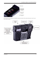
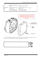
(Undefined variable: General.UserGuideTitle) sensALIGN sensor sensALIGN sensor contains two position detectors, which measure the exact position and inclination of the laser beam as the shafts are rotated. Integrated in the sensor is Bluetooth technology for wireless transmission of measurement data to ROTALIGN touch computer. sensALIGN sensor also transmits sensALIGN laser data to the computer. The intelligent sensALIGN sensor technology is used to determine shaft rotational angle and machine vibration.
(Undefined variable: General.UserGuideTitle) The four beam adjustment LEDs provide additional help when adjusting the laser beam position on sensALIGN sensor position detectors. The LEDs indicate the angle and position at which the laser beam enters the sensor. The LEDs blink either red or green depending on the angle at which the laser beam strikes the sensor. Green indicates a small angle while red indicates a large angle that must be corrected before beginning measurement.
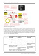
(Undefined variable: General.UserGuideTitle) sensALIGN rechargeable battery Both sensALIGN laser and sensALIGN sensor are powered using the sensALIGN rechargeable battery. The battery is charged via the charger/adapter socket using the sensALIGN charger/adapter. If the battery capacity is greater than 50% [acceptable capacity for measurement], the battery status LED on both sensALIGN laser and sensor lights up green for 2 seconds on switching on.
(Undefined variable: General.UserGuideTitle) Blinks green when charging Charging bat- Lights steady green when tery fully charged Lights red when a failure occurs during charging Blinks green when charging Lights steady green when fully charged Lights red when a failure occurs during charging LED off To replace the rechargeable batteries, use the provided 2.5 mm allen key [0 0739 1055] to undo the two hex screws that affix the battery to either sensALIGN laser or sensor.
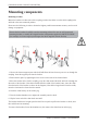
(Undefined variable: General.UserGuideTitle) Mounting components Mounting brackets Mount the brackets on either side of the coupling on either the shafts or on the solid coupling hubs, and both at the same rotational position.
(Undefined variable: General.UserGuideTitle) Mounting sensALIGN sensor and laser Mount sensALIGN laser on the support posts of the bracket fixed on the shaft of the left machine (usually reference machine), and sensALIGN sensor on the support posts of the bracket fixed on the shaft of the right machine (usually moveable machine) – as viewed from normal working position.
(Undefined variable: General.UserGuideTitle) Dimensions screen 1) Grayed out icons are disabled within the active screen. The 'Measure' icon is enabled after all dimensions have been entered. 2) Tap the measurement units icon to set desired units. Tap the dimension fields and enter all required dimensions. The user may elect to tap the ‘Next’ button to proceed to enter next dimension. Dimensions may be entered only when the dimension field is highlighted green. The rotate view icon the display.
(Undefined variable: General.UserGuideTitle) Thermal growth1 The Thermal growth screen is accessed by tapping "More". Thermal growth values can be entered only when the type of mounting is either machine feet or bearing or V-shaped support. To enter any specified thermal growth value at the required feet position, tap the corresponding value box then proceed to enter the thermal growth value using the onscreen keyboard.
(Undefined variable: General.UserGuideTitle) Initializing sensor The hint "Communication error" [1] suggests that the sensor has not been initialized although the laser beam may have been correctly adjusted. Tap either the detector area [2] or the sensor/laser area [3]to access the menu item 'Sensor list'. Tap menu item 'Sensor list' [1] to view scanned sensors. The hint 'Bluetooth scanning started' [2] appears during the scanning process.
(Undefined variable: General.UserGuideTitle) Laser beam adjustment Here is some general text for a topic. Replace this with your own content.
(Undefined variable: General.UserGuideTitle) XY View The XY View function is used to facilitate the centering of the laser beam on the two sensALIGN sensor detector planes before proceeding with measurement. 1) Tap the detector area shown to directly access the XY View screen. 2) The XY View screen may be accessed indirectly using the menu item "XY View" which appears when the "sensor/laser area is tapped.
(Undefined variable: General.UserGuideTitle) If the laser beam status is "OK" or "Centered" [1] tap "Set to zero" [2] to set the XY values of the two detector planes to 0,0. These values are then monitored to check the stability of the values. Tap "Absolute" to return to the absolute values.
(Undefined variable: General.UserGuideTitle) 18 Edition: (Undefined variable: General.
(Undefined variable: General.UserGuideTitle) Measurement modes The following measurement modes are available for horizontal machine configurations: IntelliSWEEP – This is the measurement mode used to measure standard coupled machines. It detects error influences such as coupling play, rough rotation and environmental vibration, and automatically eliminates the induced errors.
(Undefined variable: General.UserGuideTitle) In the above example, Multipoint measurement has been selected. The quality of the measurement may be displayed either as a measurement standard deviation1 (SD) or measurement quality2 factor. The averaging is set by tapping the 'Averaging' button. Averaging In certain industrial conditions, it may be necessary to increase the number of measurements (recorded laser pulses) to be averaged when taking readings to attain the desired accuracy.
(Undefined variable: General.UserGuideTitle) Multipoint measurement This mode is used to measure shafts which are either difficult to turn continuously or allow measurement only in certain rotational positions.
(Undefined variable: General.UserGuideTitle) 1) Rotational arc showing points taken and rotational angle covered by the shafts.
(Undefined variable: General.UserGuideTitle) Live Move screen Live Move is monitored in both horizontal (H) and vertical (V) planes simultaneously. 1) Tap the ‘V’ icon to follow the vertical foot corrections. 2) Tap the ‘H’ icon to follow the horizontal foot corrections 3) Tap the 'V/H' icon to follow both vertical and horizontal foot correction in 2-D simultaneously. 4) Arrows indicate direction and magnitude to move machine feet. 5) Tolerance coded gap and offset coupling values.
(Undefined variable: General.UserGuideTitle) If the laser beam is not centered, tap the detector area on the screen [1] to access the XY View. Correct the alignment condition by shimming and moving the machines laterally following the bold vertical [2] and horizontal [3] arrows. Machines should be moved to within acceptable tolerances indicated by a happy smiley [ ] or an OK icon [ ] while observing shaft alignment best practices. The system monitors both horizontal and vertical Live Move concurrently.
(Undefined variable: General.UserGuideTitle) Soft foot Soft foot measurement can be started from any screen where the 'Soft foot' icon [ Tap ] is active. to start soft foot measurement. The laser beam must be centered. Refer to Laser beam adjustment. Tap any one of the four pulsating value fields to start soft foot measurement at the respective machine foot. Loosen the corresponding foot bolt (see hint 2). The recorded soft foot value is displayed [1].
(Undefined variable: General.UserGuideTitle) 26 Edition: (Undefined variable: General.
(Undefined variable: General.UserGuideTitle) Glossary B Batch target A special target that lets you build and/or publish multiple other targets in a single group (or "batch"). You can schedule batches to run at any time. Block snippet A snippet that is created out of one or more paragraphs. C Condition tag A marker that you can apply to different areas of your content so that some sections show up in some of your outputs but not in others.
(Undefined variable: General.UserGuideTitle) S Single-Sourcing "Single-Sourcing" is a fancy term that means something very simple—to produce multiple outputs from one source. Snippet A pre-set chunk of content that you can use in your project over and over. Snippets are similar to variables, but snippets are used for longer chunks of content that you can format just as you would any other content in your topic.
(Undefined variable: General.UserGuideTitle) Topic A chunk of information about a particular subject. Topics are the most important part of a project. Everything else is contained within topics (e.g., hyperlinks, text, pictures) or points toward topics (e.g., table of contents, index, browse sequences). The very reason end users open a Help system is to find information, a little direction. They find that help within individual topics.
Empty page