
- Prozone Ozone/Salt Chlorinator Owner's Manual


9
O
z
o
n
e
F
l
o
w
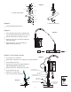
Water Flow
Injector
Open Port
(Diagram 5)
·
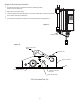
Assemble 2nd Saddle Clamp (View C)
(Diagram 6)
·
Insert 3 inch white PVC pipe into top of Saddle Clamp,
push pipe through Saddle clamp into hole in return line
·
Place two metal clamps on remaining ¾” hose line
·
Attach one end of hose to top of Salt Cell, tighten with
metal clamp (View D)
·
Attach other end of ¾” hose to 3 inch PVC pipe,
tighten with metal clamp (View D)
(Diagram 7) Ozone System Connection
·
Cut 6 inch piece of ¼” braded hose
·
Attach longer ¼” braded hose to ozone fitting on top of CSS10 Power Box
·
Secure with black hose clamp
·
Insert check valve in other end of longer braided hose,
make sure the air flow is correct (View B)
·
Attach 6 inch piece of ¼” braided hose to check valve
·
Secure with black hose clamp
·
Attach end of ¼” braided hose to
open port on top of injector (Diagram 8)
Rubber Bushing
1 1/2" Adapter
– Upper
Neoprene Gasket
7/8" Dia. Hole
1 1/2" Adapter
– Lower
Lower Saddle Clamp
Nut (2)
PVC Pipe
Gasket Foot (2)
Neoprene Gasket
Upper Saddle Clamp
Screw (2)
Washer (2)
Return Flow to Pool Return Flow to Pool
Heater
Filter
C
SS
Comp lete Sani tatio n Sy stem
™
Automa ted Syst em Co ntro l
O
ZONE
S
ALT/
C
HLORINATOR
S
YSTEM
C
SS
Comp lete Sani tati on Sy stem
™
Autom ated Syst em C ontro l
OZONE SALT/CHLORINATOR SYSTEM
View "B"
...............
Air Flow
1/4" Polybraid Hose
from Check Valve to Injector
Water Flow
..................
1/4" Polybraid Hose
from Ozonator to Check Valve
Saddle Clamp
&
Injector Assembly
Pool Return Line after Pump
1/4" Check Valve
(See "B")
3/4" Clear Vinyl
Bypass Hose
20264 PN
Diagram 5
2” Saddle Clamp Assembly
1.5” Saddle Clamp Assembly
Diagram 6
Diagram 7
Diagram 8