
- Prozone Ozone/Salt Chlorinator Owner's Manual


11
L3
L4
L5
L6
L7
L8
L9
L10
L11
L12
L13
L14
L15
L16
L17
L18
L19
L20
L21
Cell Bottom
PN600211
C
SS
Com plete San itati on S ystem
™
Auto mated Sys tem Contr ol
O
ZONE
S
ALT/
C
HLORINATOR
S
YSTEM
L22
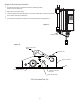
Cell Electrical Conections
"View A"
CSS 10 Unit in Bypass Configuration Shown
Properly Mounted in Vertical Position
.
.
.
.
.
.
.
.
.
.
.
.
.
.
.
Air Flow
L1
L2
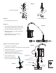
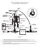
1. A stream of water is pulled out of the main line through the Venturi Bypass Assembly. (L14)
2. As water passes through the injector (L15) ozone is being injected through the mixing port of the Venturi Injector (L11)
3. This water enters the Salt Chlorine Generator Cell through the bottom of the Cell (L18 & L19).
4. A low voltage DC current is applied to the plates. The electrolysis process transforms this salt water into hyprochlorous acid,
which is your active sanitizer.
5. This sanitized\ozonated water flows out the top of the Chlorine Generator Cell (L22) back in to the main return line (L9)
through the second stage of the Bypass assembly (L7 & L8)
Diagram A-1
PN20264
PN202199
PN20260
PN20260
PN20214
PN600002
Saddle Clamp Assy.
PN20067
PN7510T-42IA-P19
PN201155