CSS 10 Complete Sanitation System Ozone/Salt Chlorinator Prozone Pool Products Huntsville, AL 35805 256-539-4570 www.prozoneint.com Owner’s Manual OPERATING INSTRUCTIONS & INSTALLATION GUIDE Introduction…………………………………………………………....… 2 How Does It Work…………………………………………………………. 2 Safety Warnings ……………………………………………………………. 2 Parts List …………………………………………………………………. 3 Important Notes …………………………………………………………. 3 Initial Salt Dosage……………………………………………………….. 4 Initial Salt Dosage Chart …………………………………………………..
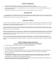
INSTRUCTION MANUAL 1. 2. 3. 4. Before performing any installation or operation, please read the enclosed instructions carefully. This manual contains easy to follow step-by-step instructions and procedures to properly install and operate your new system. The CSS-10 is electrically powered – electrical installation should be by a licensed electrician – ensure all electrical connections are proper before operating this system.
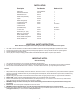
PARTS LISTING Description Part Number Number in kit CSS10 Box Salt Generator Bracket Salt Generator Cell Saddle Clamp Assembly Injector Plastic Clamp (black) ¾” Metal Hose clamp ¼” Braided Hose ¼” Braided Hose (Cell Maintenance) ¾” Clear Hose Check Valve (1/4” by ¼”) White ½” by 3” PVC Pipe Gasket, Saddle Clamp Gasket, Saddle Clamp, Barb Gasket, Saddle Foot 7S10T-42IA-P19 202199 600211 201155 600002 20185 20067 20260 1 1 1 2 1 4 4 120 inches 20260 20264 20214 20314 400078 400076 400018 24 inches 120
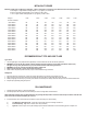
INITIAL SALT DOSAGE Maintain a salinity level of 2,000 ppm to 2,500 ppm. Refer to chart below. Pool gallons can be determined from the following formulas: a. Rectangular – Length x Width x Average Depth x 7.5 (for gallons) or 1000 for liters. b. Round – Diameter x Average depth x 5.9 (for gallons) or 785 for liters. c. Oval – Length x Width x Average Depth x 6.7 (for gallons) or 893 for liters.
ACID WASH FOR REMOVAL OF CALCIUM DEPOSITS ON CELL PLATES WARNING: FOR QUALIFIED POOL PROFESSIONALS ONLY DO NOT ATTEMPT THIS PROCEDURE WITHOUT PROPER TRAINING CAUTION: USE PROTECTIVE EYE WEAR, GLOVES, AND PROTECTIVE CLOTHING 1. 2. 3. 4. Turn PUMP OFF and allow water to drain back out of the cell and by-pass system. Disconnect the ¼” BRAIDED HOSE from the Venturi Injector.
WARRANTY Conditions: The system carries a complete two (2) year warranty against manufacturing defects. 1. On site labor, service calls or freight charges are the responsibility of the purchaser. Under no circumstances shall the manufacturer be liable for incidental or consequential damages, inconveniences or expenses in connection with removal or replacement of equipment. 2.
CSS 10 Complete Sanitation System Ozone/Salt Chlorinator Prozone Pool Products Huntsville, AL 35805 256-539-4570 www.prozoneint.com Owner’s Manual QUICK START INSTRUCTION GUIDE Please see www.prozoneint.
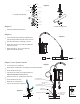
Before installing this product, turn pump off (Diagram 1) CSS 10 Mounting Instructions ·· · CSS 10 Power Box Diagram 1 CSS Complete Sanitation System ™ Automated System Control Salt Generator Cell OZONE SALT/CHLORINATOR SYSTEM Mount CSS10 in vertical position to a flat surface above the return line to you pool Position Salt Generator Cell in Mounting bracket attached to bottom of Control Box, with wire connector leads at bottom Position loose mounting bracket over top of Salt Generator Cell and fast
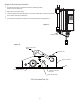
PVC Pipe Screw (2) Diagram 5 Washer (2) Upper Saddle Clamp Rubber Bushing 1 1/2" Adapter – Upper Neoprene Gasket 1.5” Saddle Clamp Assembly 7/8" Dia.
· ·· ·· (Diagram 9) Electrical System Connection Connect power lead wires from CSS10 Control Box to matching lead wires at bottom of salt cell (Diagram 9) Plug power cord in to power supply It is recommended to have pump and CSS10 on same timer so that unit is on when pump is running CSS Complete Sanitation System Automated System Control Turn on Power switch at top of CSS10 Box You must push in knob and turn clockwise to select chlorine production level (Diagram 10) OZONE SALT/CHLORINATOR SYSTEM Diag
CSS 10 Unit in Bypass Configuration Shown Properly Mounted in Vertical Position L22 L1 PN20264 L21 .... . .... PN202199 Air Flow ...... L20 PN20260 L2 Cell Electrical Conections C SS Complete Sanitation System "View A" ™ Automated System Control OZONE SALT/CHLORINATOR SYSTEM L3 L19 PN600211 Cell Bottom PN7510T-42IA-P19 L4 L18 L5 L17 L7 L6 PN20260 PN20214 L16 PN600002 Saddle Clamp Assy. L13 L1 L12 5 L10 L8 PN20067 PN201155 L9 L14 L11 Diagram A-1 1. 2. 3. 4.
WATER CHEMISTRY CHLORINE PRODUCTION AND CONTROL Free Chlorine: A ‘free’ Chlorine residual of 0.5ppm to 1.5ppm should be maintained at all times. This will vary only with respect to bathers in the pool, debris falling into the pool, and the pools overall temperature. These factors will affect the demand for chlorine and also the water ‘balance’ and ‘filtration’ effectiveness (refer to the equipment manufactures specifications with regard to the maximum chlorine level permissible).
Total Alkalinity (TA): 1. The total Alkalinity is a measurement of all the alkalis in your pool water such as Carbonates, Bicarbonates and Hydroxides, and their ability to resist change in the pH. 2. When adjusted within the acceptable levels, TA acts as a pH buffer, resisting rapid changes to pH. The recommended TA level of your pool is from 75 to 170ppm depending on the pool finish. A typical level is in the 80 ppm range. Calcium Hardness: 1.