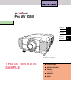
® Pro AV 9350 ✽ Projection lens is optional. THIS IS TENTATIVE SAMPLE.
TO THE OWNER Before operating this projector, read this manual thoroughly and operate the projector properly. This projector provides many convenient features and functions. Operating the projector properly enables you to manage those features and maintains it in better condition for a considerable time. Improper operation may result in not only shortening the product-life, but also malfunctions, fire hazard, or other accidents.
SAFETY PRECAUTIONS All the safety and operating instructions should be read before the product is operated. Read all of the instructions given here and retain them for later use. Unplug this projector from AC power supply before cleaning. Do not use liquid or aerosol cleaners. Use a damp cloth for cleaning. This projector should be operated only from the type of power source indicated on the marking label.
COMPLIANCES Federal Communication Commission Notice This equipment has been tested and found to comply with the limits for a Class A digital device, pursuant to Part 15 of FCC Rules. These limits are designed to provide reasonable protection against harmful interference when the equipment is operated in a commercial environment.
TABLE OF CONTENTS FEATURES AND DESIGN 6 PREPARATION 7 COMPUTER MODE SELECTING COMPUTER SYSTEM NAME OF EACH PART OF THE PROJECTOR SETTING-UP THE PROJECTOR CONNECTING THE AC POWER CORD LENS INSTALLATION POSITIONING THE PROJECTOR LENS SHIFT ADJUSTMENT PICTURE LEVEL AND TILT ADJUSTMENT MOVING THE PROJECTOR 7 8 8 9 9 9 10 10 COMPATIBLE COMPUTER SPECIFICATIONS PC ADJUSTMENT PICTURE IMAGE ADJUSTMENT NORMAL FUNCTION PICTURE POSITION ADJUSTMENT AUTO IMAGE FUNCTION PICTURE SCREEN ADJUSTMENT VIDEO MODE CONN
FEATURES AND DESIGN This Multimedia Projector is designed with the most advanced technology for portability, durability, and ease of use. The projector utilizes built-in multimedia features, a palette of 16.77 million colors, and matrix liquid crystal display (LCD) technology. ◆ Compatibility This projector widely accepts various video and computer input signals including; ● Computers IBM-compatible and Macintosh computers up to 1280 x 1024 resolution. ● 6 Color Systems NTSC, PAL, SECAM, NTSC 4.
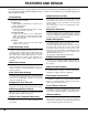
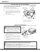
PREPARATION NAME OF EACH PART OF THE PROJECTOR FRONT OF THE CABINET SPEAKERS INFRARED REMOTE RECEIVER POWER CORD CONNECTOR PROJECTION LENS MAIN ON / OFF SWITCH LENS COVER CARRYING HANDLE LEVEL AND TILT ADJUST HANDLE BACK OF THE CABINET EXHAUST VENT INFRARED REMOTE RECEIVER HOT AIR EXHAUSTED ! Air blown from the exhaust vent is hot. When using or installing the projector, the following precautions should be taken. ● Do not put a flammable object near this vent.
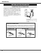
PREPARATION SETTING-UP THE PROJECTOR CONNECTING THE AC POWER CORD This projector uses nominal input voltages of 100-120 V or 200-240 V AC. The projector automatically selects the correct input voltage. It is designed to work with singlephase power systems having a grounded neutral conductor. To reduce the risk of electrical shock, do not plug into any other type of power system. Consult your authorized dealer or service station if you are not sure of the type of power supply being in use.
PREPARATION LENS INSTALLATION Before setting up the projector, install the Projection Lens on the Projector. 1. Before installation, check where the projector is used and prepare suitable lens. For specifications of the Projection Lens, refer to the manual separately attached or contact the sales dealer where you purchased the projector. 2. For installation, refer to the installation manual supplied to the Projector.
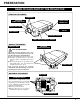
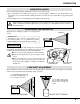
PREPARATION PICTURE LEVEL AND TILT ADJUSTMENT Picture tilt and projection angle can be adjusted with handles on both sides of the projector. Projection angle can be adjusted to 5.7 degrees upper way. 1 Press the knob on the handle. The handle pop out. 2 Turn the handles (right and left) until the picture is projected on proper position. Adjust height of rear adjustable feet by rotating them until projector properly stabled on the table. 3 Press knob and retract the handle. REAR ADJUSTABLE FEET.
CONNECTING THE PROJECTOR TERMINALS OF THE PROJECTOR This projector applies various input/output terminals and 4 terminal slots for expansion to tune to diversity of signals from computers and video equipment. 4-built-in Terminal Slots enable you to arrange desired combinations of input sources just by changing Terminal Boards. For Terminal Boards, contact the sales dealer where you purchased the projector. NOTE; DVI Terminal is unavailable for INPUT 3 and INPUT 4 slots.
CONNECTING THE PROJECTOR INPUT/OUTPUT TERMINALS AND JACKS INPUT 2 INPUT 1 INPUT 1/2/3/4 DVI INPUT TERMINAL Connect the component video output (Cr, Y, Cb or Pr, Y, Pb) from the video equipment to the R/Pr, G/Y and B/Pb jacks or connect the computer output [5 BNC Type (Red, Green, Blue, Horiz. Sync and Vert. Sync.)] from the computer to the R/Pr, G/Y, B/Pb, H/HV and V jacks. (Refer to P14, 15) serial port IN AUDIO INPUT JACKS Connect the computer output (Digital/Analog DVI-I type) to this terminal.
CONNECTING THE PROJECTOR USB PORT SERIAL PORT IN TERMINAL This port is used to control the projector with the computer. It is also used to control the computer with the Remote Control of this projector. (Refer to P40, 42.) Connect the USB port of the computer to this port. If you control the projector by computer, you must connect a cable (not provided) from your computer to this terminal.
CONNECTING THE PROJECTOR CONNECTING TO THE COMPUTER Cables used for connection (✽ = Cables are not supplied with this projector.) • VGA Cable (HDB 15 pin) NOTE : • Control Cable for PS/2 port, Serial port, or ADB port When connecting the cable, the power cords of • MAC/VGA Adapter both the projector and the external equipment should be disconnected from AC outlet. Turn the • DVI Cable projector and peripheral equipment on before the • BNC Cable (BNC x 5) ✽ computer is switched on.
CONNECTING THE PROJECTOR CONNECTING TO THE VIDEO EQUIPMENT Cables used for connection NOTE : When connecting the cable, the power cords of both the projector and the external equipment should be disconnected from AC outlet. Turn the projector and peripheral equipment on before the computer is switched on. • Video Cable (BNC x 1, BNC x 2 or BNC x 3) ✽ • S-VIDEO Cable ✽ • Audio Cable (RCA x 2) ✽ (✽ = Cables are not supplied with this projector.) Component video output equipment.
BEFORE OPERATION SIDE CONTROLS AND INDICATORS REAR INDICATORS SIDE CONTROLS FRONT INDICATORS SIDE CONTROLS ZOOM BUTTONS FOCUS BUTTONS VOLUME BUTTONS POWER ON–OFF BUTTON Used to adjust zoom. (P24) Used to adjust focus. (P24) Used to adjust volume. (P26) Used to turn the projector on or off. (P23) zoom focus volume power MENU BUTTONS LENS SHIFT BUTTONS Used to open or close the MENU operation. (P20, 21, 22) SELECT BUTTON Used to select LENS SHIFT function.
BEFORE OPERATION INDICATORS FRONT INDICATORS lamp status ready lamp replace warning temp. LAMP REPLACE INDICATOR WARNING TEMP. INDICATOR READY INDICATOR LAMP INDICATOR This LAMP REPLACE indicator lights yellow when any of Projection Lamps is nearing its end, and flashes when any of them becomes out. Check which lamp needs to be replaced on Lamp Status Display. (P44) This indicator flashes red when internal projector temperature is too high.
BEFORE OPERATION OPERATION OF THE REMOTE CONTROL LEFT SIDE INPUT 1/2 BUTTON POWER ON-OFF BUTTON on Used to select input source either INPUT 1 or INPUT 2. (P26) power focus zoom volume lock all off mute d.zoom input 1/2 POINT BUTTON Used to select MENU operation. (P20, 21, 22) menu input 3/4 SELECT BUTTON When using the Remote Control Unit, turn this switch to “ON.” And turn it to “ALL OFF” when it is not used. INPUT 3/4 BUTTON Used to select input source either INPUT 3 or INPUT 4.
BEFORE OPERATION ZOOM BUTTON power Used to adjust zoom. (P24) focus zoom volume Operating Range VOLUME BUTTON lock Used to adjust volume. (P26) FOCUS BUTTON mute d.zoom input 1/2 Used to adjust focus. (P24) menu input 3/4 D.ZOOM BUTTON Point the remote control toward the projector (Receiver Window) whenever pressing the buttons. Maximum operating range for the remote control is about 16.4’ (5m) and 60° in front and rear of the projector.
BEFORE OPERATION OPERATING ON-SCREEN MENU HOW TO OPERATE THE ON-SCREEN MENU You can control and adjust this projector through the ON-SCREEN MENU. Refer to the following pages to operate each adjustment in the ON-SCREEN MENU. WIRELESS REMOTE CONTROL POINT BUTTON Used to move the Pointer UP/ DOWN/ RIGHT/ LEFT. 1 MOVING THE POINTER Move the pointer (see the NOTE below) by pressing POINT button(s) on the SIDE CONTROL or the REMOTE CONTROL. 2 SELECT THE ITEM Select the item by pressing SELECT button.
BEFORE OPERATION MENU BAR MENU BAR IN COMPUTER MODE WHEN SELECT THE DVI TERMINAL INPUT MENU IMAGE MENU PC ADJUST MENU SETTING MENU Used to select the Input source. (Refer to P26) Used to adjust the computer image. [Fine sync / Total dots / White Balance / Contrast / Brightness / Sharpness/ Gamma/Progressive] (Refer to P32) Used to adjust the parameters to match with the input signal format.
BEFORE OPERATION MENU BAR IN VIDEO MODE WHEN SELECT THE AV TERMINAL INPUT MENU IMAGE MENU SETTING MENU Used to select the Input source. (Refer to P26) Used to adjust the picture image. [Color / Tint / White Balance / Contrast / Brightness/ Sharpness/Gamma / Noise Reduction / Progressive] (Refer to P37) Used to set the Display Menu, other functions setting and reset Lamp Replacement Monitor Timer. (Refer to P39-41) LANGUAGE MENU Used to select the language used in the Menu.
BASIC OPERATION TURNING ON / OFF THE PROJECTOR TURNING ON THE PROJECTOR 1 Complete the peripheral connections (with Computer, VCR, etc.) before turning on the projector. (Refer to "CONNECTING TO THE PROJECTOR" on Pages 12~15 for connecting that equipment.) 2 Connect the projector's AC Power Cord into a wall outlet and turn the MAIN ON / OFF SWITCH to ON. The LAMP indicator lights RED, and the READY indicator lights GREEN.
BASIC OPERATION ADJUSTING THE IMAGE ZOOM ADJUSTMENT 1 Press the ZOOM ▲/▼ button(s) on the Side Control or on the Remote Control Unit. The message “Zoom” is displayed. 2 Press the ZOOM ▲ button to make the image larger, and press the ZOOM ▼ button to make the image smaller. Zoom The message disappears after 4 seconds. FOCUS ADJUSTMENT 1 Press the FOCUS ▲/▼ button(s) on the Side Control or on the Remote Control Unit. The message “Focus” is displayed.
BASIC OPERATION BLANK FUNCTION Press the BLANK button on the Remote Control Unit to black out the image. This function is cancelled when the BLANK button is pressed again or any other function button is pressed. Blank The message disappears after 4 seconds. PICTURE FREEZE FUNCTION Press the FREEZE button on the Remote Control Unit to freeze the picture on-screen. This function is cancelled when the FREEZE button is pressed again or any other function button is pressed.
BASIC OPERATION MENU OPERATION 1 2 Press the MENU button and the ON-SCREEN MENU will appear. Press the POINT LEFT/RIGHT buttons to select SOUND and press the SELECT button. Another dialog box SOUND ADJUST Menu will appear. Indicate the roughly level of the item. Press the POINT DOWN button and a red-arrow icon will appear. Move the arrow to the item that you want to select by pressing the POINT UP/DOWN buttons. Move the arrow to ▲ or ▼ and press the SELECT button.
COMPUTER MODE SELECTING COMPUTER SYSTEM WHEN SELECT THE INPUT 1 (DVI SLOT ) When connecting to the computer, select a computer signal type (Digital or Analog) in INPUT SOURCE Menu. 1 Press the MENU button and the ON-SCREEN MENU will appear. Press the POINT LEFT/RIGHT buttons to select INPUT SOURCE and press the SELECT button. Another dialog box INPUT SOURCE Menu will appear. 2 Press the POINT DOWN button and a red-arrow icon will appear.
COMPUTER MODE AUTOMATIC MULTI-SCAN SYSTEM This projector automatically tunes to most different types of computers based on VGA, SVGA, XGA or SXGA (refer to “COMPATIBLE COMPUTER SPECIFICATION” on page 29). When selecting Computer, this projector automatically tunes to the incoming signal and projects the proper image without any special settings. (Setting of the Computer System may be required when connecting some computers.) SYSTEM BOX Display the SYSTEM being selected.
COMPUTER MODE COMPATIBLE COMPUTER SPECIFICATIONS Basically this projector can accept the signal from all computers with the V, H-Frequency mentioned below and less than 202 MHz of Dot Clock.
COMPUTER MODE PC ADJUSTMENT This Projector can automatically tune to the display signals from most personal computers currently distributed. However, some computers employ special signal formats which are different from the standard ones and may not be tuned by the Multi-Scan system of this projector. If this happens, the projector cannot reproduce a proper image and the image may be recognized as a flickering picture, a non-synchronized picture, a non-centered picture or a skewed picture.
COMPUTER MODE Total lines The number of the total vertical lines. Adjust the number to match the image of your personal computer. Total dots The number of the total dots in one horizontal period. Adjust the number to match the image of your computer. Horizontal / Vertical Adjustment of the horizontal or vertical picture position. When the image is not centered on the screen, adjust each of those items. Clamp Adjustment of the clamp level. When the image has a dark bar(s), try this adjustment.
COMPUTER MODE PICTURE IMAGE ADJUSTMENTS 1 Press the MENU button and the ON-SCREEN MENU will appear. Press the POINT LEFT/RIGHT buttons to select IMAGE and press the SELECT button. Another dialog box PICTURE IMAGE ADJUSTMENT Menu will appear. 2 Press the POINT DOWN button and a red-arrow icon will appear. Move the arrow to the function that you want to select and then press SELECT button. Standard Normal picture level preset on this projector. This picture level can be set by pressing the NORMAL button.
COMPUTER MODE NORMAL FUNCTION The normal picture level is preset on this projector at the factory and can be restored anytime you press the NORMAL button (located on the Side Control or on the Remote Control Unit). The “Standard” display will be displayed on the screen for a few seconds. Standard PICTURE POSITION ADJUSTMENT The position of the image can be adjusted vertically and horizontally through PICTURE POSITION ADJUSTMENT. 1 Press the MENU button and the ON-SCREEN MENU will appear.
COMPUTER MODE PICTURE SCREEN ADJUSTMENT This projector has a picture screen resize function, which enables you to display the desirable image size. 1 Press the MENU button and the ON-SCREEN MENU will appear. Press the POINT LEFT/RIGHT buttons to select SCREEN and press the SELECT button. Another dialog box PICTURE SCREEN Menu will appear. 2 Press the POINT DOWN button and a red-arrow icon will appear. Move the arrow to the function that you want to select and then press SELECT button.
VIDEO MODE SELECTING VIDEO SOURCE WHEN SELECT THE INPUT 2 (5 BNC TERMINAL ) When connecting to those equipment, select the type of Input source in INPUT SOURCE Menu. 1 Press the MENU button and the ON-SCREEN MENU will appear. Press the POINT LEFT/RIGHT buttons to select INPUT SOURCE and press the SELECT button. Another dialog box INPUT SOURCE Menu will appear. 2 Press the POINT DOWN button and a red-arrow icon will appear. Move the arrow to "Y, Pb/Cb, Pr/Cr" and then press the SELECT button.
VIDEO MODE SELECTING COLOR SYSTEM 1 Press the MENU button and the ON-SCREEN MENU will appear. Press the POINT LEFT/RIGHT buttons to select SYSTEM and press the SELECT button. Another dialog box VIDEO SYSTEM Menu will appear. 2 Press the POINT DOWN button and a red-arrow icon will appear. Move the arrow to "Auto", and then press the SELECT button. WHEN SELECT THE INPUT 3 (AV TERMINAL ) Auto The projector automatically detects the incoming Video system, and adjusts itself to optimize its performance.
VIDEO MODE PICTURE IMAGE ADJUSTMENT 1 Press the MENU button and the ON-SCREEN MENU will appear. Press the POINT LEFT/RIGHT buttons to select IMAGE and press the SELECT button. Another dialog box PICTURE IMAGE ADJUSTMENT Menu will appear. 2 Press the POINT DOWN button and a red-arrow icon will appear. Move the arrow to the function that you want to select and then press SELECT button. Standard Normal picture level preset on this projector. This picture level can be set by pressing the NORMAL button.
VIDEO MODE NORMAL FUNCTION The normal picture level is preset on this projector at the factory and can be restored anytime you press the NORMAL button (located on the Side Control or on the Remote Control Unit). The "Standard" display will be displayed on the screen for a few seconds. Standard PICTURE SCREEN ADJUSTMENT This projector has a picture screen resize function, which enables you to display the desirable image size. 1 Press the MENU button and the ON-SCREEN MENU will appear.
SETTING SETTING MENU 1 Press the MENU button and the ON-SCREEN MENU will appear. Press the POINT LEFT/RIGHT buttons to select SETTING and press the SELECT button. Another dialog box SETTING Menu will appear. 2 Press the POINT DOWN button and a red-arrow icon will appear. Move the arrow to the item that you want to set, and then press the SELECT button to set it (For example "On" or "Off").
SETTING On start When this function is “On” the projector is automatically turned on just by switching the MAIN ON / OFF SWITCH on. NOTE: Be sure to turn the projector off properly (refer to the section “TURNING OFF THE PROJECTOR” on page 23). If the projector is turned off in the wrong steps, the On Start function does not operate properly. Lamp Mode This Projector is equipped with 4 Projection Lamps and the number of using lamps can be switched to 4 lamps or 2 lamps.
SETTING Lamp replacement monitor timer Be sure to reset the Lamp Replacement Monitor Timer when the Lamp Assembly is replaced. When the Lamp Replacement Monitor Timer is reset, the LAMP REPLACEMENT indicator stops lighting. 1 Turn the projector on, and press the MENU button and the ONSCREEN MENU will appear. Press the POINT LEFT/RIGHT buttons to select SETTING and press the SELECT button. Another dialog box SETTING MENU will appear. 2 Press the POINT DOWN button and a red-arrow icon will appear.
APPENDIX OPERATING WIRELESS MOUSE The Wireless Remote Control Unit is not only able to operate the projector but also usable as a wireless mouse for most Personal Computers. The POINT buttons and the two CLICK buttons are used for the wireless mouse operation. The wireless mouse is available only when PC mouse pointer is displayed on the screen. When the menu or the indicator of the projector is displayed on the screen instead of the PC mouse pointer, the wireless mouse cannot be used.
APPENDIX MAINTENANCE TEMPERATURE WARNING INDICATOR The TEMPERATURE WARNING Indicator flashes red when the internal temperature of the projector exceeds the normal temperature. The Indicator stops flashing when the temperature of the projector returns to normal. When the TEMPERATURE WARNING Indicator continues to flash, check the items listed below. 1 2 3 The Ventilation slots of the projector may be blocked. In such an event, reposition the appliance so that the ventilation slots are not obstructed.
APPENDIX LAMP MANAGEMENT This Projector is equipped with 4 Projection Lamps to ensure brighter image and those lamps are controlled by Lamp Management Function. Lamp Management Function detects the status of all lamps and shows the status on screen or on the LAMP REPLACE indicator. This function also automatically controls the Lamp Mode when any of lamps is out for the end of life or malfunctions.
APPENDIX LAMP REPLACEMENT CAUTION ● For continued safety, replace with a lamp assembly of the same type. ● Allow the projector to cool for at least 45 minutes before you open the lamp cover. The inside of the projector can become very hot. ● Do not drop the lamp assembly or touch the glass bulb! The glass can shatter and may cause injury. Follow these steps to replace the lamp assembly. 1 Check the number of lamp to be replaced on Lamp Status Display.
APPENDIX TROUBLESHOOTING Before calling your dealer or service station for assistance, check the items below once again. 1. Make sure you have connected the projector to your equipment as described in section "CONNECTING THE PROJECTOR" on pages 12 ~ 15. 2. Check cable connections. Verify that all computer, video and power cords are properly connected. 3. Verify that power is switched on. 4. If the projector still does not display an image, re-start the computer. 5.
APPENDIX Problem: Try these Solutions: Picture is L/R Reversed. Check Ceiling/Rear feature. (See "SETTING" section on page 39). Picture is T/B inverted. Check Ceiling feature. (See "SETTING" section on page 39). Some displays are not seen during the operation. Check Display feature. (See "SETTING" section on page 39). ● ● ● ● No sound. Remote control unit does not work. Wireless mouse function does not work. Check audio cable connection from audio input source. Adjust audio source.
APPENDIX TECHNICAL SPECIFICATIONS Projector Type Multi-media Projector Dimensions (W x H x D) 22.9" (581 mm) x 10" (252 mm) x 30.9" (783 mm) Net Weight 78.4 Ibs (35.5 kg) LCD Panel System 1.8" TFT Active Matrix type x 3 panels Number of Pixels 2,359,296 {786,432 (1,024 x 768) x 3} Color System 6 color system (PAL, SECAM, NTSC, NTSC4.43, PAL-M and PAL-N) TV Signal 480i, 480p, 575i, 575p, 720p, 1035i, 1080i-50 and 1080i-60 Scanning Frequency H-sync. 15 ~ 120 KHz, V-sync.
APPENDIX CONFIGURATIONS OF THE TERMINALS DVI-I TERMINAL (DIGITAL/ANALOG) This terminal accepts only Digital (TMDS) or Analog (RGB) output signal. Connect the display output terminal of the computer to this terminal with the DVI cable (supplied). Pin Configuration C1 C2 1 2 3 4 5 6 7 8 9 10 11 12 13 14 15 16 17 18 19 20 21 22 23 24 C3 C4 C5 C1 C2 C3 C4 C5 Analog Red Input Analog Green Input Analog Blue Input Analog Horiz. sync Analog Ground (R/G/B) 1 2 3 4 5 6 7 8 T.M.D.S. Data2– T.M.D.S. Data2+ T.M.D.
APPENDIX SERIAL PORT IN/OUT TERMINAL Pin Configuration Connect the serial port output terminal of the computer to this terminal with the Serial Cable (not supplied). 5 4 3 2 1 9 8 7 6 1 2 3 4 5 6 7 8 9 ----RxD TxD ----Ground ----------------- USB PORT TERMINAL Pin Configuration Connect the USB port output terminal of the computer or peripheral equipment to this terminal with the USB port Cable (not supplied).
APPENDIX Warranty Proxima warrants that the Proxima® Model Pro AV 9350 product manufactured by Proxima is free from defects in materials and workmanship under normal use during the Warranty Period. The Warranty Period commences on the day of purchase by the end-user. The Warranty Period is two years. The projector lamp is not covered by this Warranty. Each Proxima product is manufactured from new parts, or new and some used parts.
For Americas: Proxima 9440 Carroll Park Drive San Diego, CA 92121 Ph: (858) 457-5500 (800) 447-7692 (U. S. and Canada.) Fax. (858) 457-9647 www.proxima.com Part No. 710-XXXXX 10/2000 610 287 0558 (1AA6P1P2361-- ML6F) For Europe, Asia, Africa, Australasia: ASK Proxima ASA K. G. Meldahlsvei 9 Postboks 1403 N-1602 Fredrikstad tel. +47-69 34 01 55 fax. +47-69 34 06 32 Technical Support & Service Horsterweg 24 6191 RX Beek The Netherlands tel. +31-43 358 5210 fax.