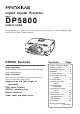
Liquid Crystal Projector Model DP5800 USER’S GUIDE Please read this user’s guide for fast setup and use of your new projector. After reading this guide, keep it in a safe place for future reference. DP5800 Features High brightness Highly efficient optical system with a metal halide lamp ensures high brightness. High resolution Three separate high-definition liquid crystal panels are used to provide sharp, clear pictures.
For Customers in the United Kingdom THIS PRODUCT IS SUPPLIED WITH A TWO-PIN MAINS PLUG FOR USE IN MAINLAND EUROPE. FOR USE IN THE U.K., PLEASE REFER TO THE NOTES ON THIS PAGE. IMPORTANT FOR THE UNITED KINGDOM The mains lead on this equipment is supplied with a moulded plug incorporating a fuse, the value of which is indicated on the pin face of the plug. Should the fuse need to be replaced, an ASTA or BSI approved BS 1362 fuse must be used of the same rating.
WARNING: This equipment has been tested and found to comply with the limits for a Class A digital device, pursuant to Part 15 of the FCC Rules. These limits are designed to provide reasonable protection against harmful interference when the equipment is operated in a commercial environment. This equipment generates, uses, and can radiate radio frequency energy and, if not installed and used in accordance with the instruction manual, may cause harmful interference to radio communications.
Safety Precautions Warnings If any unusual performance occurs. • • • An abnormal smell or smoke may indicate the possibility of fire or electric shock, etc. When any unusual performance is observed, immediately turn off the power switch and pull out the power plug from the power outlet. Check that there is no smoke, etc., and then contact your dealer to repair the unit. Do not repair it yourself .
Cautions Do not step on this unit or place a heavy object on it. • When inserting batteries in this unit, pay attention to the direction of the and polarity indications and insert the batteries correctly. If the polarities are confused, it may cause injury or damage near the unit due to burst batteries, liquid leakage, etc. not step on this unit. Pay special attention • Do if children are present. If you do, the unit may fall over or may be broken causing an injury. not put a heavy object on this unit.
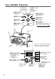
Your DP5800 Projector ON indicator STANDBY / ON button Blinks in Standby mode. Glows in operation mode. (See page 11.) Power ON/OFF button. OFF sets the unit in Standby mode. LAMP indicator Glows when the lamp should be replaced. (See page 11.) TEMP Indicator FOCUS button Glows when temperature inside the projector is too high. (See page 11.) temp lamp power Adjusts focus. ZOOM buttons zoom focus Adjust picture size. RESET button Resets unit to factory settings.
Your DP5800 Projector (continued) Remote control MENU STICK SWITCH Selects or adjusts the menu items in Menu mode. Works as the mouse in Play mode. RESET / RIGHT button STANDBY / ON button Power ON/OFF button. OFF sets the unit in Standby mode. Resets menu items to factory settings when menus are open. Works as right mouse button in Computer mode. RIGHT RIGHT RISET RESET STANDBY/ON MENU ON / OFF button MENU ZOOM button Displays or removes the on-screen menus. Adjusts picture size.
Installation Projector and screen setup Determine proper picture size and projection distance as illustrated below. Top view Side view Screen Lens center b a Screen (inches) a (inches) b (inches) Minimum Maximum 40 60 89 3.4 60 89 134 5.1 80 119 179 6.9 100 149 224 8.6 120 179 269 10.3 150 224 336 12.9 200 298 448 17.
Using the Projector Projecting the picture 4 2 7 5 2 RIGHT RISET RESET STANDBY/ON MENU 4 ZOOM 5 FOCUS VOL TIMER BLANK 1 7 POSITION MUTE VIDEO1/2 RGB1/2 3 INPUT 1 Turn the MAIN POWER switch of the projector on. [ : ON] • The ON indicator will glow orange. 2 Press the STANDBY/ON button. • The ON indicator blinks (green) and then glows (green). 3 Remove the lens cap. 4 Adjust the picture size using the ZOOM buttons. 5 Adjust the focus using the FOCUS buttons.
Using the Projector (continued) Turning off the power 1 1 RIGHT RISET RESET STANDBY/ON MENU 3 1 2 Press and hold the STANDBY/ON button for 1 second. • The ON indicator lights up orange and the lamp turns off. About 1 minute later, the fan stops and the indicator blinks orange. NOTE: If you press the STANDBY/ON button for less than 1 second, the projector will not switch to Standby mode. 2 Turn the MAIN POWER switch of the projector off. [ 3 Replace the lens cap.
Projector Messages and Indicators On screen display The following messages may be displayed on the screen. Message Action NO SIGNAL IS DETECTED Check the input signal connection. SYNC IS OUT OF RANGE The horizontal frequency of the input signal exceeds the range of the projector,and it cannot be displayed. Change the resolution of the input signal. CHANGE THE LAMP The lamp should be replaced.
Using the Menus 2, 3 2 3 1 RIGHT RIGHT RISET RESET 1 1 Press the MENU ( menu STANDBY/ON MENU ) button or the MENU ON / OFF button. • Menus are displayed on the screen. 2 Select the menu to be adjusted using the MENU ( buttons or the MENU STICK SWITCH. ) • The menu displayed in green is selected. 3 Select the item to be adjusted using the MENU ( buttons or MENU STICK SWITCH. ) • The item displayed in green can be adjusted. 4 The changes take effect.
Using the Menus (continued) SET UP Menu The SET UP menu lets you change the picture characteristics and position. The menus will be different for RGB and video signals. RGB signal Setup mumu SETUP INPUT IMAGE VOLUME BRIGHT CONTRAST V.POSIT H.POSIT H.PHASE H.SIZE VIDEO signal Setup menu (video models only) OPT. SETUP INPUT IMAGE OPT.
Using the Menus (continued) INPUT Menu Use this menu to select an input source. For Video inputs, you must also select a video format. SETUP INPUT IMAGE OPT. SETUP RGB1 RGB2 VIDEO1 VIDEO2 TEST PATTERN INPUT IMAGE RGB1 RGB2 VIDEO1 VIDEO2 TEST PATTERN Item OPT. SYSTEM AUTO NTSC PAL SECAM Options RGB1 Selects the RGB 1 terminal. RGB2 Selects the RGB 2 terminal. VIDEO1* Selects the VIDEO 1 terminal. VIDEO2* Selects the VIDEO 2 terminal. TEST PATTERN Selects the TEST PATTERN.
Using the Menus (continued) Select normal or expanded image size. SETUP INPUT DISP. SIZE IMAGE OPT. SETUP NORMAL SMALL INPUT MESSAGE Adjustment Item IMAGE OPT. TURN ON TURN OFF Details of adjustment MIRROR Inverts the picture horizontally or vertically for ceiling or rear screen projection. H : INVERT Inverts the picture horizontally. V : INTERT Inverts the picture vertically. H&V : INVERT Inverts the picture horizontally and vertically.
Using the Menus (continued) SETUP SETUP INPUT IMAGE OPT. COM. SPEED (bps) 1200 2400 4800 9600 19200 INPUT OPT. IMAGE SETUP INPUT COM. BITS SETUP INPUT LANGUAGE TIMER SETUP INPUT 10 min. IMAGE AUTO OFF IMAGE OPT. Details of adjustment COM. SPEED Select speed of data transmission. COM. BITS Select the data format. 7N1... 7 data-bits, No parity, 1 stop bit. 8N1... 8 data-bits, No parity, 1 stop bit. TIMER Sets the on-screen timer.
Connecting to a Video Source Available for video models only. 1 . Input signal specifications S-VIDEO signal Luminance signal Chrominance signal 1.0Vp-p, 75 Ω termination VIDEO signal AUDIO signal 1.0Vp-p, 75 Ω termination 0.286Vp-p (burst signal), 75 Ω termination Input 200mVrms, 20 kΩ below (MAX 3.0Vp-p) Output 0~200mVrms, 1k Ω 2 .
Connecting to an RGB Signal (continued) 3 . Example of computer signal Interlaced / Non-interlaced Computer/Signal source Resolution H×V fH (kHz) fV (Hz) 15kHz RGB (NTSC) — 15.7 60 VGA-1 (IBM compatible) 640 × 350 31.5 70.1 H, V separate H: Positive V: Negative Non-interlaced VGA-2 (IBM compatible) 640 × 400 31.5 70.1 H, V separate H: Negative V: Positive Non-interlaced VGA-3 (IBM compatible) 640 × 480 31.5 59.
Connecting to an RGB Signal (continued) 4 . Initial signal settings The following signals are initially set. The settings may need to be changed for specific computer types. Use the Setup menu (page 16) to adjust the settings. b a DATA HSYNC c d Horizontal Timing (µs) Computer/Signal sorce a b d 15kHz RGB 9.8 52.7 4.7 63.6 VGA-1 5.7 25.2 3.8 31.8 VGA-2 5.7 25.2 3.8 31.8 VGA-3 5.7 25.2 3.8 31.8 Mac 13inch mode 5.3 21.2 2.1 28.6 VESA (72Hz) 5.4 20.5 1.3 26.
Connecting to a Control Signal 1 . CONTROL terminal Mouse . Pin No RS232C PS/2 ADB 1 Serial TDM 2 CLK 3 DATA SDATA 4 5 6 SEL0 SEL0 SEL0 7 SEL1 SEL1 SEL1 8 READY D-sub 15 pin terminal (Male) 9 10 GND GND GND +5V +5V GND 11 12 13 RDP 14 TDP 15 Caution Turn off the power of both the projector and computer before connecting to the CONTROL port. Connect the computer to the CONTROL terminal of the projector using an appropriate cable.
Connecting to a Control Signal (continued) PS/2 mouse Projector 1 CLK 2 DATA 3 4 5 SEL0 6 SEL1 7 8 9 GND 10 11 +5V 12 13 14 15 ADB (Mac) mouse Projector 1 SDATA 2 3 4 5 SEL0 6 SEL1 7 8 9 GND 10 11 +5V 12 13 14 15 Serial mouse Projector TDM 1 2 3 4 5 SELO 6 SEL1 7 READY 8 9 GND 10 11 12 13 14 15 Computer 1 2 3 4 5 6 DATA Mini Din 6pin GND +5V CLK 6 5 4 3 1 2 PS/2 cable Computer 1 2 3 4 ADB (POWER ON) GND +5V Mini Din 4pin 4 3 1 2 ADB cable Computer 1 2 3 4 5 6 7 8 9 CD RD TD DTR G
Connecting to a Control Signal (continued) 3 . Communication settings (1) Connect the projector and computer using an RS 232C cable. (2) Turn on the computer. After the computer is fully started, turn on the projector. (3) Start communication. Projector Computer 1 2 3 4 5 6 7 8 9 GND 10 11 12 RDP 13 TDP 14 15 1 2 3 4 5 6 7 8 9 CD RD TD DTR GND DSR RTS DTS RI D-sub 9pin 2 1 6 3 7 4 8 5 9 RS232C cable 4 .
Connecting to a Control Signal (continued) Control data table Item Data code MOUSE 00h=stop mouse emulation.
Connecting to a Control Signal (continued) Procedure for checking projector status. 1. The computer sends the command ’20H’ + ‘yyH’ to the projector. 2. The projector replies with the command ‘1xH’ + ‘yyH’ + data bytes. Procedure for setting projector status 1. The computer sends the command ‘3xH’ + ‘yyH’ + data bytes. 2. The projector changes its status. 3. The projector replies with the command ‘1xH’ + ‘yyH’ + data bytes to indicate its newstatus.
System Setup Typical system connections: AC Outlet VCR with S-VHS out (video models only) Computer (Notebook type) Computer (Desktop type) VCR, etc. (video models only) CRT Display Caution Turn power off to all devices before connecting. Refer to the instruction manual for each device before connecting.
Cleaning the air filter Clean the air filter about every 100 hours of operation. 1 2 Turn off the MAIN POWER switch of the projector and pull out the power cord. Remove the air filter from the bottom. 2 3 Clean the air filter using a vacuum cleaner. If dirt is still present, wipe the air filter with a cloth moistened with water, or use a neutral detergent and wipe the filter dry with a dry cloth. 4 Re-install the air filter. Caution If the air filter is filled with dust, etc.
Troubleshooting Check the following before asking for service. If trouble continues, call your dealer or Proxima Technical Support. Phone: 619-457-5500, Worldwide Web: http://www.proxima.com Problem Possible Cause Action Page • The Main power is not turned on. • Turn the MAIN POWER switch on. 9 • The power cord is disconnected. • Insert the power cord into an AC socket. 6 • The setting of the input source is not correct.
Specifications • All specifications are subject to change without notice. Product type Liquid crystal projector Model name DP5800 Display system 3 sheets of liquid crystal panels, 3 primary color lights shutter system Liquid crystal panel Panel size 1.3 inches Drive system TFT active matrix Number of pixels (H800 x V600) 480,000 pixels Lens Zoom lens F=2.3 ∼ 3.
Warranty and Servicing Please read this operating guide before calling for service. For warranty and service claims, please contact Proxima Corporation Proxima Corporation Main Office Proxima Europe LTD. 9440 Carroll Park Drive San Diego, CA 92121-2298 U.S.A. Phone (619) 457-5500 Fax (619) 457-9647 http://www.proxima.com St.