Part Number 73082/1 Tsunami MP.11 Antenna Installation Guide Version 2.
Tsunami MP.11 Antenna Installation Copyright © 2003, 2004, 2005 Proxim Wireless Corporation, San Jose, CA. All rights reserved. Covered by one or more of the following U.S. patents: 5,231,634; 5,875,179; 6,006,090; 5,809,060; 6,075,812; 5,077,753. This manual and the software described herein are copyrighted with all rights reserved.
Tsunami MP.11 Antenna Installation Contents ABOUT THIS BOOK ........................................................................................................................................... 4 Who Should Use This Guide ......................................................................................................................... 4 Finding Additional Information.......................................................................................................................
Tsunami MP.11 Antenna Installation About This Book This Antenna Installation Guide explains how to install and set up an outdoor antenna with the 5054, 5054-R, and 2454-R hardware. This guide does not explain how to erect antenna masts, nor how to install a safety grounding system. These prerequisites must be in place before installing the directional antenna. See Tsunami MP.11 Recommended 5 GHz and 2.
Tsunami MP.11 Antenna Installation FINDING ADDITIONAL INFORMATION Installing Hardware Antennas typically are used in combination with Tsunami MP.11 systems. The hardware installation of these devices is described in the Installation and Management manual included with each product. Configuration and Management Configuration and management of outdoor wireless links is accomplished with management tools that come with the systems.
Tsunami MP.11 Antenna Installation ABOUT THE TSUNAMI MP.11 PRODUCT FAMILY The Tsunami MP.11 models let you set up a wireless system based upon two basic topologies: • A point-to-point link, which lets you set up a connection between two locations as an alternative to: º º • Leased lines in building-to-building connections Wired Ethernet backbones between wireless access points in difficult-to-wire environments A single point-to-multipoint network, which lets you connect more than two buildings.
Tsunami MP.11 Antenna Installation SAFETY PRECAUTIONS Read this section carefully before beginning the installation. All of the following requirements should be satisfied prior to starting installation of your outdoor antennas. DANGER! The outdoor antennas to be used with this product are intended for mounting on a roof or on the side of a building. Any person not trained or experienced in this type of work should not attempt this installation.
Tsunami MP.11 Antenna Installation Chapter 1. Preparing for Installation Plan the day for your outdoor antenna installation carefully. Do not install the antenna in wet or windy conditions, during a thunderstorm, or when the area in which the equipment is to be installed is covered with ice or snow. The grounding system for the antenna mast, radio hardware, and surge arrestor should be installed before the cable from the antenna is connected to the surge arrestor.
Tsunami MP.11 Antenna Installation SITE PREREQUISITES Review all requirements outlined in this chapter before starting the installation procedure.
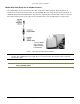
Tsunami MP.11 Antenna Installation Model 5054 Cable Setup for an Outdoor Antenna The following figure shows an overview of the cable setup for the outdoor antenna. When the 5054 is not mounted close to where the antenna cable enters the building (where the surge arrestor must be mounted), an additional cable between the 5054 and the surge arrestor is required, plus a female-female converter connector.
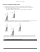
Tsunami MP.11 Antenna Installation Model 2454-R and Model 5054-R Hardware The following types of hardware devices are used for setting up a wireless link: • • Base Station Unit (BSU) Subscriber Unit (SU) There are two models of the 5054-R and 2454-R Subscriber Unit—one with an integrated antenna, another similar in appearance to the Base Station Unit, also with an external antenna connection, as shown in the following illustration.
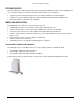
Tsunami MP.11 Antenna Installation The electronics (power supply and radio) are designed for indoor mounting and operation. The ideal location must satisfy the following requirements: • The location provides a connection to a grounding type AC wall outlet (100-240 VAC), using the standard power cord supplied with the unit. (Alternative power can be provided through Power over Ethernet.
Tsunami MP.
Tsunami MP.11 Antenna Installation CAUTION! • The cable must be secured along the complete distance between attachment points. No part of the antenna cable should be allowed to hang free. This is particularly important for outdoor cable parts. • The antenna cable and cable connectors are not designed to withstand excessive force: º º º Do not use the connectors as ‘cable grips’ to pull cable through raceways or conduits.
Tsunami MP.11 Antenna Installation The definition of the 1st Fresnel zone is an imaginary boundary line offset along the direct signal path. This boundary is defined as the point where if a signal were reflected between the two antennas, it would travel a distance exactly one-half wavelength longer than the direct-path signal. Each succeeding Fresnel zone boundary adds an additional half-wavelength to the reflected path distance between the antennas.
Tsunami MP.11 Antenna Installation To minimize the influence of obstacles, signal interference, or reflections, note the following guidelines: • Mount the antenna as high as possible above the ground to allow maximum clearance: º º In open areas, ground is the actual surface of the earth. In dense urban areas, ground is to be interpreted as the height of the highest obstacle in the signal path between the two antenna sites.
Tsunami MP.11 Antenna Installation Mounting the Antenna As the mounting procedures for the various antennas differ from one another, consult the documentation you received from the manufacturer for mounting procedures. Proxim Wireless Corporation offers multiple antennas to set up a wireless link (as well as a unit with an integrated antenna).
Tsunami MP.11 Antenna Installation Connecting the Antenna Cable Once the antenna is properly installed, you can connect the antenna to the unit by way of the surge arrestor: 1. Connect the antenna cable to the antenna. 2. Secure the antenna cable to the mast so that the cable connectors do not support the full weight of the cable. 3. Connect the opposite end of the antenna cable to the surge arrestor (see “Surge Arrestor Installation” Error! Bookmark not defined.).
Tsunami MP.11 Antenna Installation 3. To protect the weatherproofing stretch tape from the effects of Ultra-Violet (UV) radiation (for example, from direct sunlight), you should protect the joint with two half-overlapped layers of any vinyl plastic electrical tape. Alternatively, you can apply silicone sealer to protect the weatherproofing tape from sunlight, rain and other weather conditions.
Tsunami MP.11 Antenna Installation Antenna Alignment Display Feature Antenna alignment is a process to physically align the antennas of both units to have the best possible radio link established between them. The antenna alignment process usually is performed during installation and after major repairs.
Tsunami MP.11 Antenna Installation Antenna Alignment Commands set aad enable local Enables display of the local SNR. Local SNR is the SNR measured by the receiver at the near end. set aad enable remote Enables display of the remote SNR. Remote SNR is the SNR as measured by the receiver at the far end. set aad enable average Enables display of the average SNR. The average SNR is the average of the local and remote SNR. set aad disable Disables Antenna Alignment Display (Ctrl-C also disables AAD).
Tsunami MP.11 Antenna Installation Antenna Cable Routing The antenna cable must be routed and fixed in such a way that installation technicians have a clear passage area. All connectors that are located outdoors must have a weatherproof seal. You are advised to seal connectors only after you have completed the final radio test. BEFORE CLIMBING THE ROOF... Before you start the installation, check whether you have all the required components to set up an outdoor wireless link.
Tsunami MP.11 Antenna Installation Chapter 2. Determining Range and Clearance When you read about wireless outdoor products, you often encounter the terms output power of the radio and gain of the antenna equipment as measures for the strength of the transmitted signal. • Output power of radio equipment often depends on maximum limits as defined by local radio regulations; consequently, output power is, by definition, not the way to enhance wireless performance.
Tsunami MP.11 Antenna Installation Maximum Range The maximum range of your system is based upon: • • • The type of outdoor antenna equipment The data speed of the wireless link The clearance of the signal path (see “Clearance Factor” below). The values in this section are based upon calculations that assume optimal radio conditions. They do not represent a guarantee that the same maximum distance can be achieved at your location.
Tsunami MP.11 Antenna Installation If any significant part of this bulged zone is obstructed, a portion of the radio energy is lost, which can affect the performance of your wireless link in terms of maximum range and transmit rate.
Tsunami MP.11 Antenna Installation Figure 4. Clearance Factor Diagram DISTANCE ASSUMPTIONS AND EXPECTATIONS Model 5054 Assumptions • Point-to-multipoint configuration using USA regulations for L and U bands, ETSI regulations for M bands • Clear line-of-sight with no unusual multipath • Sector antenna (17 dBi, 60º) at Base Station with 20 feet LMR-600 cable • Three-foot parabolic dish (31.4 dBi) at Subscriber Unit with 20-foot LMR-600 cable • With a fade margin minimum of 10 dB to 2 miles, and 0.
Tsunami MP.11 Antenna Installation Model 5054-R Assumptions • Point-to-multipoint configuration using USA regulations for L and U bands, ETSI regulations for M bands • Clear line-of-sight with no unusual multipath • Sector antenna (17 dBi, 60º) at Base Station with short 6 ft LMR-600 (1 dB loss) jumper cable • Standard integrated antenna for Subscriber Unit • With a fade margin minimum of 10 dB to 2 miles, and 0.2 dB additional fade margin for every 0.
Tsunami MP.11 Antenna Installation CALCULATIONS Availability of the microwave path is a prediction of the percent of time that the link operates without producing an excessive bit error rate (BER) due to multipath fading.
Tsunami MP.11 Antenna Installation Procedure 1. Start with the transmit power and the number of the channel to be used. From the output power tables on page 30 find the dBm associated with this output power and channel. 2. Subtract the total loss of all transmission elements between the antenna and the radio on one side of the link (dB). 3. Add the dBi of the antenna you will be using. The total is the EIRP (equivalent isotropically radiated power). 4.
Tsunami MP.11 Antenna Installation Notes: • The RSL must be higher than the Receiver Sensitivity plus the fade margin for a good link. See Table 1 to have a working link with no excessive errors. The amount of Fade Margin indicates the reliability of the link; the more Fade Margin, the more reliable the link. • The path loss must be smaller than the link budget minus the minimum required fade margin. The maximum ranges cause the path loss plus the fade margin to be the same as the link budget.
Tsunami MP.11 Antenna Installation Table 2. Distance and Link Budget Reference Frequency: 5600 MHz Center Frequency for Europe Link Budget (dB) Distance (m) Fresnel Zone Link Budget (m) (dB) Distance (m) Fresnel Zone Link Budget (m) (dB) Distance (km) Fresnel Zone (m) 61 4.8 0.3 91 151 1.4 121 4.8 8.0 62 5.4 0.3 92 170 63 6.0 0.3 93 190 1.5 122 5.4 8.5 1.6 123 6.0 64 6.8 0.3 94 9.0 214 1.7 124 6.8 65 7.6 0.3 9.5 95 240 1.8 125 7.6 10.1 66 8.5 0.
Tsunami MP.11 Antenna Installation Chapter 3. Antenna Cabling System INTRODUCTION As radio regulations differ between the various countries worldwide, not all of the outdoor solutions described in this manual may be allowed in the country where you plan to install this equipment.
Tsunami MP.11 Antenna Installation SELECTING THE CORRECT CONNECTOR TYPE The following are differences between the Tsunami MP.11 Model 5054 and Model 5054-R: • Male versus Female N-type connector • Indoor install and long coax versus Outdoor install and short coax • Low-loss antenna coax versus outdoor-rated Ethernet cable and surge arrestor All cabling components of the outdoor antenna system come with standard-N type connectors as depicted in the following table. Table 3.
Tsunami MP.11 Antenna Installation Check with a qualified electrician if you are in doubt as to whether the surge arrestor and cable connectors are properly grounded. Only after you have verified that each of the items is properly grounded, replace the surge arrestor and disconnect the cables from the grounding system in exactly the reverse order of the previous steps.
Tsunami MP.11 Antenna Installation Specifications Part number Frequency range VSWR Insertion loss Impedance DC breakdown voltage Impulse breakdown voltage Insulation resistance Maximum withstand current Clamping voltage (PoE,Data) Connectors Cable type Dimensions Weight Operating Temperature Grounding 5054-SURGE DC~ 5.875 GHz 1.25 : 1 Max.@ DC~4 GHz 1.45 : 1 Max.@ 4~5.875 GHz 0.5 dB Min.@ DC~5.
Tsunami MP.11 Antenna Installation Support and Warranty If you are having a problem using a Proxim product and cannot resolve it with the information in the product documentation, gather the following information and contact Proxim Technical Support: • • • • What kind of network are you using? What were you doing when the error occurred? What error message did you see? Can you reproduce the problem? Be sure to obtain an RMA number before sending any equipment to Proxim for repair.
Tsunami MP.11 Antenna Installation WARRANTY AND REPAIR If it appears that your unit needs a repair or replacement, return the unit to your Dealer or Distributor in its original packaging.
Tsunami MP.