Tsunami MP.11 and MP.
Tsunami MP.11and MP.11a Installation and Management COPYRIGHT ©2003 Proxim Corporation, Sunnyvale, CA. All rights reserved. Covered by one or more of the following U.S. patents: 5,231,634; 5,875,179; 6,006,090; 5,809,060; 6,075,812; 5,077,753. This manual and the software described herein are copyrighted with all rights reserved.
Tsunami MP.11and MP.11a Installation and Management Contents Copyright.........................................................................................................................................2 Trademarks.....................................................................................................................................2 FCC COMPLIANCE........................................................................................................................2 CHAPTER 1. OVERVIEW..
Tsunami MP.11and MP.11a Installation and Management Radio Specifications ...................................................................................................................110 APPENDIX B. TROUBLESHOOTING.............................................................................................111 LED Indicators ............................................................................................................................111 MP.11/a Connectivity Issues .........................
Tsunami MP.11and MP.11a Installation and Management Chapter 1. Overview The Tsunami MP.11 and MP.11a are flexible wireless outdoor routers that let you design solutions for point-to-point links and point-to-multipoint networks. The Tsunami MP.11 and MP.11a are product families comprising several products (such as the MP.11 2411 Base Station and the MP.11 2411 Residential Subscriber Unit). For simplification: ▪ ▪ ▪ All products that are part of the MP.11 Product Family are referred to as MP.11.
Tsunami MP.11and MP.11a Installation and Management WIRELESS NETWORK TOPOLOGIES You can use the MP.11/a to set up the following types of topologies: ▪ ▪ Point-to-Point Link (below) Point-to-Multipoint Network (on page 7) A link between two locations always consists of a Base and a Satellite station. A station is a radio set up as either a Base Station or a (Residential) Subscriber Unit. A Base station can, depending upon its configuration, connect to one or more Satellite stations.
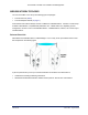
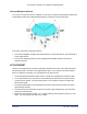
Tsunami MP.11and MP.11a Installation and Management Point-to-Multipoint Network If you want to connect more than two buildings, you can set up a single Point-to-Multipoint network with a single Base interface and multiple Satellite interfaces, as depicted in the following figure. In this figure, the system is designed as follows: ▪ ▪ The central building B is equipped with a Base interface, connected to either an omni-directional, or a wide angle antenna.
Tsunami MP.11and MP.11a Installation and Management Chapter 2. Installation This chapter describes the steps required to install the MP.11/a installation steps, such as: ▪ ▪ ▪ ▪ ▪ ▪ Identifying Network Topology and Equipment below Finding a Suitable Location on page 9 Installing the MP.11/a on page 10 Switching On the MP.11/a on page 15 Installing Documentation and Software on page 15 Mounting the MP.11/a on page 16 Note: The installation does not cover the mounting and connection of antennas.
Tsunami MP.11and MP.11a Installation and Management FINDING A SUITABLE LOCATION To make optimal use of the MP.11/a, you must find a suitable location for the hardware. The radio range of the MP.11/a largely depends upon the position of the antenna. Proxim recommends you do a site survey, observing the following requirements, before mounting the MP.11/a hardware. ▪ The location must allow easy disconnection of the unit from the power outlet if necessary.
Tsunami MP.11and MP.11a Installation and Management INSTALLING THE MP.11/a The MP.11/a supports two power methodsan AC power outlet and Active Ethernet. The power supply accepts an input AC voltage in the range of 100-240 VAC. The installation procedure on page 11 provides instructions for attaching both the power and Ethernet connectors. In situations without an external antenna (for example, during a desk tryout), the antenna cable is not required.
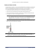
Tsunami MP.11and MP.11a Installation and Management Installation Procedure To install the MP.11/a: 1. Unpack the unit and accessories from the shipping box. The MP.11/a kit contains the following items: 3 2 3 1 4 5 Shown in picture: 1 2 3 4 5 Tsunami MP.11/a unit Mounting Stand Documentation and Software CD-ROM Wall mounting hardware Power supply with power cord The shipment also includes the Tsunami MP.11/a Quick Install Guide and the Tsunami MP.11/a Release Notes. 2.
Tsunami MP.11and MP.11a Installation and Management 3. Unlock the unit’s cable cover. To release the cable cover, press down on the cable cover lock located in the front center of the unit. 4. Remove the cable cover. 5. Remove the front cover from the unit (the side with the LED indicators, shown in the figure on left); then remove the back cover (figure on right). Chapter 2.
Tsunami MP.11and MP.11a Installation and Management 6. Connect the grounding wire to the MP.11/a using the Faston plug on the metal case, next to the power plug. 7. Connect one end of an Ethernet cable to the Ethernet port. The other end of the cable should not be connected to another device until after installation is complete. º Use a straight-through Ethernet cable if you intend to connect the MP.11/a to a hub, switch, patch panel, or Active Ethernet power injector.
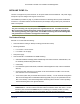
Tsunami MP.11and MP.11a Installation and Management 11. Place the unit in the final installation location (see “Mounting the MP.11/a” on page 16 for details). 12. Replace the back cover, front cover, and cable cover. Be careful to avoid trapping the antenna, power, and Ethernet cables when replacing the cable cover. Attaching a Kensington Security Lock (Optional) If so desired, you can attach a Kensington lock to secure the cable cover into place. This protects the unit from unauthorized tampering.
Tsunami MP.11and MP.11a Installation and Management SWITCHING ON THE MP.11/a The MP.11/a can be powered by a power supply or by Active Ethernet through an Active Ethernet splitter. Depending upon the powering method, you can switch the MP.11/a on by: ▪ ▪ Plugging the power cord of the power supply into an AC power outlet Connecting the Active Ethernet splitter to the Ethernet cabling When the power is switched on, the MP.11/a performs startup diagnostics.
Tsunami MP.11and MP.11a Installation and Management INSTALLING DOCUMENTATION AND SOFTWARE The MP.11/a also comes with documentation and software on a CD-ROM. To install the documentation and software on a computer or network: 1. Place the CD-ROM in a CD-ROM drive. The installer normally starts automatically. You can also start the installer manually by running the setup.exe program in the root directory of the CD-ROM. 2. Click the Install Help and Software button and perform the necessary steps.
Tsunami MP.11and MP.11a Installation and Management Wall Mounting Follow these steps to mount the MP.11/a on a wall. 1. Identify the location where you intend to mount the unit. 2. Unplug the MP.11/a’s power supply, if necessary. 3. Use a Phillips screwdriver to remove the metal base from the underside of the MP.11/a, if necessary. 4. Press down on the cable cover lock to release the cable cover (see “Installation Procedure” on page 11 for illustrations for this and the next 3 steps). 5.
Tsunami MP.11and MP.11a Installation and Management Ceiling Mounting Follow these steps to mount the MP.11/a to a ceiling. 1. Unplug the MP.11/a’s power supply, if necessary. 2. Use a Phillips screwdriver to attach the metal base to the underside of the MP.11/a, if you have not already done so. See “Installation Procedure” on page 11 for an illustration. 3. Feed a mounting screw through each of the four rubber feet. The MP.11/a comes with four 3.5 mm x 40 mm pan-head screws. 4.
Tsunami MP.11and MP.11a Installation and Management Chapter 3. Management Overview This chapter describes how to gain access to the MP.11/a for configuration and management. Three interfaces are provided for viewing or changing the MP.11/a’s settings: Web Interface on page 22 The Web Interface is a graphical interface based upon Web pages from a built-in Web server. Command Line Interface on page 23 The Command Line Interface (CLI) is a text-based interface using typed commands.
Tsunami MP.11and MP.11a Installation and Management The MP.11/a either obtains its IP address automatically through DHCP or it must be set manually. With ScanTool, you can find out the current IP address of the MP.11/a and, if necessary, change it so that is appropriate for your network. The MP.11/a is shipped with the static IP address 10.0.0.1 configured. Setting the IP Address Manually If you want to set the IP address manually: 1. Run ScanTool on a computer connected to the same LAN subnet as the MP.
Tsunami MP.11and MP.11a Installation and Management 2. Select the MP.11/a for which you want to set the IP address and click Change. The Change dialog window is displayed, as shown in the following window. 3. Ensure that Static is selected as the IP Address Type and fill in the IP Address and Subnet Mask suitable for the LAN subnet to which the MP.11/a is connected. 4. Enter the Read/Write Password (the default value is public) and click OK to confirm your changes. The respective MP.
Tsunami MP.11and MP.11a Installation and Management WEB INTERFACE OVERVIEW The Web Interface provides a graphical user interface with which you can easily configure and manage the MP.11/a. This section describes only how to access the Web Interface; the Web Interface itself described in “Chapter 4. Basic Management” on page 27 and “Chapter 5. Web Interface” on page 42. To use the Web Interface, you need only the IP address of the MP.11/a. See “MP.11/a IP Address” on page 19 for details.
Tsunami MP.11and MP.11a Installation and Management To view or change basic system information, click the Configure button on the left side of the Web interface window, then click the System tab. MP.11A OPTIONS Selecting a Country The Tsunami MP.11a provides a selectable Country field that automatically provides the allowed band and frequencies for the selected country as well as, where applicable, Dynamic Frequency Selection (DFS) and Transmit Power Control (TPC). MP.
Tsunami MP.11and MP.11a Installation and Management Transmit Power Control Transmit Power is a manual configuration selection to reduce the output power in the radio. The output power level for the operating frequency can be found in the Event Log of the MP.11a embedded software. For more information about Transmit Power Control, see “Interface Configuration: Wireless Slot” on page 34.
Tsunami MP.11and MP.11a Installation and Management Serial Port You can also use the CLI through the serial port of the MP.11/a with a terminal program such as HyperTerminal. You can use this method for cases in which other access methods cannot be used, or when the IP address of the MP.11/a cannot be set or retrieved. Also see “Hard Reset to Factory Default” on page 106. To use the CLI through the serial port of the MP.
Tsunami MP.11and MP.11a Installation and Management HyperTerminal Connection Properties The serial connection properties can be found in HyperTerminal as follows: 1. Start HyperTerminal and select Properties from the File menu. 2. In the Connect using: drop-down list, select Direct to Com1 (depending upon the COM port you use) and click Configure…; a window such as the following is displayed. 3. Make the necessary changes and click OK. 4.
Tsunami MP.11and MP.11a Installation and Management Chapter 4. Basic Management This chapter describes the initial setup of the MP.11/a, which lets you set up and monitor the basic features of the MP.11/a. In most cases, setting up these basic features is sufficient. A full overview of the Web Interface is provided in “Chapter 5. Web Interface” on page 42; “Glossary” on page 118 provides a brief explanation of the terms used.
Tsunami MP.11and MP.11a Installation and Management REBOOTING AND RESETTING All configuration changes require a restart unless otherwise stated. There are several ways to restart the MP.11/a, which are described in the following sub-sections. Applying Changes Most changes you make become effective only when the MP.11/a is rebooted. A reboot stores configuration information in non-volatile memory and then restarts the MP.11/a with the new values (see “Soft Reset to Factory Default” on page 29).
Tsunami MP.11and MP.11a Installation and Management Resetting Hardware If the MP.11/a does not respond for some reason and you are not able to reboot, you can restart by means of a hardware reset. This restarts the MP.11/a hardware and embedded software. The last saved configuration is used. Any changes that you have made since then are lost. To reset the hardware, press and release the RESET button on the MP.11/a unit with, for example, a pencil.
Tsunami MP.11and MP.11a Installation and Management SYSTEM STATUS To view the current system status, click the Status button. The Status window is the first page you see when you log in. Chapter 4.
Tsunami MP.11and MP.11a Installation and Management SYSTEM CONFIGURATION The System Configuration page lets you change the MP.11/a’s system name, location name, and so on (see the following System Configuration window). These details help you to distinguish this MP.11/a from other routers, and lets you know whom to contact in case of problems. To go to this page, click the Configure button and the System tab. These settings do not influence the operation of the MP.
Tsunami MP.11and MP.11a Installation and Management MP.11a kits sold in the United States are pre-configured to scan and display only the outdoor frequencies permitted by the FCC. No other Country selections, channels, or frequencies may be configured. MP.11a kits sold outside of the United States and Canada support the selection of a Country by the professional installer.
Tsunami MP.11and MP.11a Installation and Management IP CONFIGURATION The IP Configuration window lets you change the MP.11/a IP parameters. These settings differ when the MP.11/a is in Router mode. To go to this page, click the Configure button, the Network tab, then the IP Configuration sub-tab. If the device is configured in Bridge mode, you can set the following parameter: IP Address Assignment Type Select Static if you want to assign a static IP address to the MP.
Tsunami MP.11and MP.11a Installation and Management INTERFACE CONFIGURATION The Interfaces configuration pages let you change the MP.11/a Ethernet and wireless parameters. The Wireless tab is displayed by default when you click the Interfaces tab. Wireless To configure the wireless interface, click the Configure button followed by the Interfaces tab; then click the Wireless sub-tab.
Tsunami MP.11and MP.11a Installation and Management The fields that can be changed on this window are described in the following text. Interface Type The interface type can be Worp Satellite or Worp Base. *See “Wireless Outdoor Router Protocol” on page 38.) Base Station System Name The name found on the system page of the Base Station to which this satellite is connecting.
Tsunami MP.11and MP.11a Installation and Management Note: This feature only lets you decrease your output power; it does not let you increase your output power beyond the maximum allowed defaults for your frequency and country. Select one of the following options and click OK at the bottom of the window. Your original output power is adjusted relative to the value selected. The new setting takes effect immediately without rebooting.
Tsunami MP.11and MP.11a Installation and Management Data Rate The rate at which data is to be transferred. The default data rate is 36 Mbps. The SU must never be set to a lower data rate than the Base Station because timeouts will occur at the Base Station and communication will fail. Selections for Data Rate are as shown in the following table.
Tsunami MP.11and MP.11a Installation and Management Ethernet Port To configure the Ethernet interface, click the Configure button, the Interfaces tab, and the Ethernet sub-tab. You can set the following parameter from this tab.
Tsunami MP.11and MP.11a Installation and Management Wireless To monitor the wireless interfaces, click the Monitor button and the Wireless tab.. This tab lets you monitor the general performance of the radio and the performance of the WORP Base or WORP Satellite interfaces. Interfaces To monitor transmission details, click the Monitor button and the Interfaces tab.. The Interfaces tab provides detailed information about the MAC-layer performance of the MP.11/a interface. Chapter 4.
Tsunami MP.11and MP.11a Installation and Management SECURITY SETTINGS To prevent misuse, the MP.11/a provides wireless data encryption and password-protected access. It is important to set the encryption parameters and change the default passwords. Encryption You can protect the wireless data link by using encryption. Encryption keys can be 5 (64-bit), 13 (WEP 128-bit), or 16 (AES 128-bit) characters in length. Both ends of the wireless data link must use the same parameter values.
Tsunami MP.11and MP.11a Installation and Management Passwords Access to the MP.11/a is protected with passwords. The default password is public. Note: The asterisks displayed when you enter a password are a set number that does not necessarily equal the number of characters in the actual password string, which is intended for added security. Changing the Telnet Password To change the telnet password, click the Configure button and the Telnet tab.
Tsunami MP.11and MP.11a Installation and Management Chapter 5. Web Interface This section covers the Web Interface of the MP.11/a. The interface is described hierarchically according to these buttons, which appear on the left side of the Web page: ▪ ▪ ▪ ▪ Status Configure on page 44 Monitor on page 69 Commands on page 76 For an introduction to the basics of MP.11/a management, see “Chapter 4. Basic Management” on page 27.
Tsunami MP.11and MP.11a Installation and Management System Status In this section, the basic system status is shown, including the version number of the embedded software. Systems Traps This section shows the status of system traps. System traps occur when the MP.11/a encounters irregularities. Deleting system traps has no effect on the operation of the MP.11/a. System traps also are sent to an SNMP manager station (if so configured).
Tsunami MP.11and MP.11a Installation and Management CONFIGURE Use the Configure section to change the settings of the MP.11/a. There are ten tabs in this section. 1. 2. 3. 4. 5. 6. 7. 8. 9. 10. System below Network on page 46 Interfaces on page 50 SNMP on page 54 RIP on page 55 Telnet on page 57 Serial on page 58 HTTP on page 58 Security on page 59 Filtering on page 61 1) System The System Configuration page lets you change the MP.11/a’s System Name, Location, and so on.
Tsunami MP.11and MP.11a Installation and Management You can enter the following details: System Name This is the system name for easy identification of the MP.11/a. Use the system name of this Base Station to configure the Base Station System Name parameter on a satellite if you want the satellite to register only with this Base Station. If the Base Station System Name is left blank on the satellite, it can register with any Base Station that has a matching Network Name and Network Secret.
Tsunami MP.11and MP.11a Installation and Management 2) Network IP Configuration The IP Configuration window lets you change the MP.11/a IP parameters. These settings differ when the MP.11/a is in Router mode. Click the Configure button, the Network tab, and the IP Configuration sub-tab to view and configure local IP address information. See “Setting the IP Address Manually” on page 20 for more information.
Tsunami MP.11and MP.11a Installation and Management Default TTL The default time-to-live value. The static fields on this window are described as follows: ObjectID This field shows the OID of the product name in the MIB. Ethernet MAC Address The MAC address of the Ethernet interface of the device. Descriptor Shows the product name and firmware build version. Up Time The length of time the device has been up and running since the last reboot.
Tsunami MP.11and MP.11a Installation and Management To add entries to the table of DHCP Relay Agents, click Add Table Entries; the following window is displayed. Enter the Server IP Address and any optional comments; click Add. To edit or delete entries in the table, click Edit/Delete Table Entries; make your changes and click OK. Spanning Tree The Spanning Tree Protocol (STP) can be used to create redundant networks (“hot standby”) and to prevent loops.
Tsunami MP.11and MP.11a Installation and Management IP Routes Click the Configure button, the Network tab and the IP Routes sub-tab to configure IP routes. You cannot configure IP Routes in Bridge mode. In Routing mode, the Add Table Entries and Edit/Delete Table Entries buttons are enabled. Click the Add button to add entries; a window such as the following is displayed: Enter the route information and click Add. Click the Edit/Delete Table Entries button to make changes to or delete existing entries.
Tsunami MP.11and MP.11a Installation and Management 3) Interfaces Wireless To configure the wireless interface, click the Configure button followed by the Interfaces tab; then click the Wireless sub-tab. The wireless interface can be placed in either WORP Base or WORP Satellite mode (selected from the Interface Type drop-down box). (See “Wireless Outdoor Router Protocol” on page 68 for more information.) The wireless interface settings differ per mode.
Tsunami MP.11and MP.11a Installation and Management Base Station System Name The name found on the system page of the Base Station to which this satellite is connecting. This parameter can be used as an added security measure, and when there are multiple Base Stations in the network and you want a satellite to register with only one when it may actually have adequate signal strength for either.
Tsunami MP.11and MP.11a Installation and Management Select one of the following options and click OK at the bottom of the window. Your original output power is adjusted relative to the value selected. The new setting takes effect immediately without rebooting. Full (0 dB) Half (-3 dB) Quarter (-6 dB) Eighth (-9 dB) Minimum (-10 dB) Enable Turbo Mode (MP.11a ONLY) Check this box to enable Turbo Mode. Turbo Mode currently is supported only in the United States.
Tsunami MP.11and MP.11a Installation and Management Selections for Data Rate are as shown in the following table. Date Rate Date Rate, Turbo Enabled 6 Mbps 9 Mbps 12 Mbps 18 Mbps 24 Mbps 36 Mbps 48 Mbps 54 Mbps 12 Mbps 18 Mbps 24 Mbps 36 Mbps 48 Mbps 72 Mbps 96 Mbps 108 Mbps Satellite Density The Satellite Density setting is a valuable feature for achieving maximum bandwidth in a wireless network. It influences the receive sensitivity of the radio interface.
Tsunami MP.11and MP.11a Installation and Management You can set the Configuration parameter: Select from these settings for the type of Ethernet transmission (Configuration drop-down box): 10 Mbit/s – half-duplex 10 Mbit/s – full-duplex 10 Mbit/s – auto-duplex 100 Mbit/s – half-duplex 100 Mbit/s – full-duplex autospeed – half-duplex autospeed – auto-duplex Half-duplex means that only one side can transmit at a time. Full-duplex allows both sides to transmit.
Tsunami MP.11and MP.11a Installation and Management 5) RIP Routing Internet Protocol (RIP) is a dynamic routing protocol you can use to help automatically propagate routing table information between routers. The Tsunami MP.11/a can be configured to use either RIPv1, RIPv2, RIPv1 Compatible, or a combination of all three versions, while operating in Router mode. In general, the Tsunami MP.11/a RIP module is based upon RFC 1389.
Tsunami MP.11and MP.11a Installation and Management The following table describes the properties and features of each version of RIP supported in the Tsunami MP.11/a.
Tsunami MP.11and MP.11a Installation and Management RIP Notes ▪ Ensure that routers on the same physical network are configured to use the same version of RIP. ▪ Routing updates occur every 30 seconds. It may take up to 3 minutes for a route that has gone down to timeout in a routing table. ▪ RIP is limited to networks with 15 or fewer hops. 6) Telnet Click the Configure button and the Telnet tab to manage telnet parameters, including password and timeout. Chapter 5.
Tsunami MP.11and MP.11a Installation and Management Note: To use HyperTerminal for CLI access, make sure to check “Send line ends with line feeds” in the ASCII Setup window (click Properties from the HyperTerminal window; select Setup, then ASCII Setup. See “HyperTerminal Connection Properties” on page 26 for more information). 7) Serial Click the Configure button and the Serial tab to change the serial port settings.
Tsunami MP.11and MP.11a Installation and Management 9) Security MAC Authentication Click the Configure button, the Security tab, and the MAC Auth sub-tab to build a list of authorized wireless stations that can register at the MP.11/a and access the network. This feature is supported on the wireless interface and only wireless MAC addresses should be entered in the list. For example, build a list of the wireless MAC addresses on the Base Station for the authorized satellites.
Tsunami MP.11and MP.11a Installation and Management RADIUS Authentication Click the Configure button, the Security tab, and the Radius Auth sub-tab to set the IP address of the RADIUS server containing the central list of MAC addresses allowed to access the network. In large networks with multiple MP.11/a devices, you can maintain a list of MAC addresses on a centralized location using a RADIUS authentication server that grants or denies access.
Tsunami MP.11and MP.11a Installation and Management 10) Filtering Click the Configure button and the Filtering tab to configure packet filtering. Packet filtering can be used to control and optimize network performance. Filtering sub-tabs are as follows: Ethernet Protocol The Ethernet Protocol Filter blocks or forwards packets based upon the Ethernet protocols they support.
Tsunami MP.11and MP.11a Installation and Management Ethernet Protocol Filtering Blocks or forwards packets based upon the Ethernet protocols they support: Ethernet: Packets are examined at the Ethernet interface. Wireless: Packets are examined at the Wireless interface. All Interfaces: Packets are examined at both interfaces. Disabled: The filter is not used. Filter Operation Type Passthru: Only the enabled Ethernet Protocols listed in the Filter Table pass through the bridge.
Tsunami MP.11and MP.11a Installation and Management Static MAC Pair Filtering The Static MAC Address Filter optimizes the performance of a wireless (and wired) network. Click the Configure button, the Filtering tab, and the Static MAC Pair Filtering sub-tab to access the Static MAC Address Filter. The filter is an advanced feature that lets you limit the data traffic between two specific devices (or between groups of devices based upon MAC addresses) through the wireless interface of the MP.11/a.
Tsunami MP.11and MP.11a Installation and Management Storm Threshold Click the Configure button, the Filtering tab, and the Storm Threshold sub-tab to prevent broadcast/multicast overload. Storm Threshold is an advanced Bridge setup option that you can use to protect the network against data overload by specifying: ▪ A maximum number of frames per second as received from a single network device (identified by its MAC address). ▪ An absolute maximum number of messages per port.
Tsunami MP.11and MP.11a Installation and Management Broadcast Protocol Filtering Click the Configure button, the Filtering tab, and the Broadcast Protocol Filtering sub-tab to deny specific IP broadcast, IPX broadcast, and multicast traffic. Click the Edit Table Entries button to display an editable window such as the following. You can configure whether this traffic must be blocked for Ethernet to wireless, wireless to Ethernet, or both. Chapter 5.
Tsunami MP.11and MP.11a Installation and Management IP Access Table Entries in this table show which wireless stations are allowed to use SNMP, HTTP, and telnet management interfaces. To add an entry, click the Add Table Entries button, specify the IP address and mask of the wireless stations to which you want to grant access, and click Add. For example, 172.17.23.0/255.255.255.0 allows access from all wireless stations with an IP address in the 172.17.23.xxx range.
Tsunami MP.11and MP.11a Installation and Management ADDITIONAL INTERFACE INFORMATION Dynamic Frequency Selection (Tsunami MP.11a only) With Tsunami MP.11a units, Dynamic Frequency Selection (DFS) is enabled automatically based upon the country you select. You can tell DFS is in use because the frequency selection drop-down box on the Interfaces page is grayed out (click the Configure button and the Interfaces tab); it displays only the DFS-selected frequency.
Tsunami MP.11and MP.11a Installation and Management 2. Guarantee the efficient use of available frequencies by all devices in a certain area. To meet this requirement, the BSU scans each available frequency upon startup and selects a frequency based upon the least amount of noise and interference detected. This lets multiple devices operate in the same area with limited interference.
Tsunami MP.11and MP.11a Installation and Management Warning! When the remote interface accidentally is set at too small a value and communication is lost, it cannot be reconfigured remotely and a local action is required to bring the communication back. Therefore, the best place to experiment with the level is at the unit that can be managed without going through the link; if the link is lost, the setting can be adjusted to the correct level to bring the link back.
Tsunami MP.11and MP.11a Installation and Management WORP Click the Monitor button and the WORP tab to monitor the performance of the WORP Base or WORP Satellite interfaces. Possible values for the Registration Last Reason field are as follows: 1 = Successful registration 2 = Maximum number of satellites reached 3 = Authentication failure 4 = Reserved for future use 5 = No response from satellite within the Registration Timeout Period 6 = Reserved for future use Chapter 5.
Tsunami MP.11and MP.11a Installation and Management 2) ICMP Click the Monitor button and the ICMP tab to view the number of ICMP messages send and received by the MP.11/a. It includes ping, route, and host unreachable messages. 3) Radius Click the Monitor button and the Radius tab to view information about the traffic exchanged with a RADIUS server. 4) Per Station Click the Monitor button and the Per Station tab to view the following information: Chapter 5.
Tsunami MP.11and MP.11a Installation and Management 5) Features Click the Monitor button and the Features tab to view the following information: Note: A Base Station shows how many WORP satellites it can support; the Subscriber Unit and Residential Subscriber Unit will show how many Ethernet hosts they support on their Ethernet port as the “Max Users on Satellite” parameter.
Tsunami MP.11and MP.11a Installation and Management All stations displayed after “Explore” come up “Disabled.” Select a station by changing Disabled to Start and click the Link Test button. You can change multiple stations to Start, but only the last station in the list is displayed as the remote partner when you click the Link Test button. See the following figure: The Link Test provides the following information: Link Test stops when you close the Link Test page. Chapter 5.
Tsunami MP.11and MP.11a Installation and Management 7) Interfaces Click the Monitor button and the Interfaces tab to view detailed information about the IP-layer performance of the MP.11/a interfaces. There are two sub-tabs: Wireless and Ethernet. The following figure shows the Wireless interface; the same information is provided for the Ethernet interface on the Ethernet sub-tab.
Tsunami MP.11and MP.11a Installation and Management 9) IP Routes Click the Monitor button and the IP Routes tab to view all active IP routes of the MP.11/a. These can be either static or dynamic (obtained through RIP). This tab is available only in Router mode, and you can add routes only when in Router mode. 10) Learn Table Click the Monitor button and the Learn Table tab to view all MAC addresses the MP.11/a has detected on an interface. The Learn Table displays information relating to network bridging.
Tsunami MP.11and MP.11a Installation and Management COMMANDS This section describes the commands that you can perform with the Web Interface. There are five tabs in the Commands section. 1) Download Click the Commands button and the Download tab to download image, configuration, and license files to the MP.11/a. Server IP address Enter the TFTP Server IP address. (Double-click the TFTP server icon on your desktop and locate the IP address assigned to the TFTP server.
Tsunami MP.11and MP.11a Installation and Management 2) Upload Click the Commands button and the Upload tab to upload a configuration file from the MP.11/a. 3) Reboot Click the Commands button and the Reboot tab to restart the embedded software of the MP.11/a. Configuration changes are saved and the MP.11/a is reset. CAUTION: Rebooting the unit causes all users currently connected to lose their connection to the network until the MP.1/a1 has completed the restart process and resumed operation. Chapter 5.
Tsunami MP.11and MP.11a Installation and Management 4) Reset Click the Commands button and the Reset tab to restore the configuration of the MP.11/a to the factory default values. You can also reset the MP.11/a from the RESET button located on the side of the unit. Because this resets the MP.11/a’s current IP address, a new IP address must be assigned. CAUTION: Resetting the MP.11/a to its factory default configuration permanently overwrites all changes made to the unit. The MP.
Tsunami MP.11and MP.11a Installation and Management Chapter 6. Command Line Interface The Command Line Interface (CLI) provides a text-based interface with which you can configure and manage the MP.11/a using commands. You can enter these commands or submit them in the form of a script to allow batch processing. Accessing the CLI is discussed in “Command Line Interface Overview” in the Tsunami MP.11/a Installation and Management Guide.. Administrators use the CLI to control MP.
Tsunami MP.11and MP.11a Installation and Management CLI TERMINOLOGY Configuration Files Database files containing the current configuration. Configuration items include the IP address and other network-specific values. Config files can be downloaded to the MP.11/a or uploaded for backup or troubleshooting. Download versus Upload Downloads transfer files to the MP.11/a. Uploads transfer files from the MP.11/a. The TFTP server performs file transfers in both directions.
Tsunami MP.11and MP.
Tsunami MP.11and MP.11a Installation and Management ? (Question Mark) You can show CLI help by entering help at the command prompt. The CLI also provides context-specific help. For help in a specific situation, enter ?. You can get help as follows: display the command list ? display commands that start with specified letters s? display parameters for set and show commands display prompts for successive parameters The more letters you enter, the fewer the results returned.
Tsunami MP.11and MP.11a Installation and Management To transfer a file from the TFTP server to the MP.11/a: download where can be one of these four values: config - Configuration file, the current settings of the MP.11/a image - Image file, embedded software for the MP.
Tsunami MP.11and MP.11a Installation and Management History Command Use the history command to show this list of commands. Commands entered in the current session are stored in a Command History Buffer. To avoid re-entering long command statements, use the keyboard up arrow (↑) and down arrow ( ↓) keys to recall previous statements from the Command History Buffer. When the desired statement reappears, press the Enter key to execute, or you can edit the statement before executing it.
Tsunami MP.11and MP.11a Installation and Management Quit Command The quit, done, and exit commands are used to disconnect and close the current CLI session. Reboot Command Use the reboot command to signal the MP.11/a to reboot after a specified number of seconds. reboot The parameter must be positive. Specify a value of 0 (zero) for an immediate reboot. Save Command Use the save command to save the current configuration of the MP.11/a to flash memory.
Tsunami MP.11and MP.11a Installation and Management Show Command The show command lets you view parameter and statistical values. You can view a single parameter, a group of parameters, or a table with parameters. (A table consists of rows with similar parameters.) To see a definition and syntax example, enter only show. To see a list of available parameters, enter a question mark after show (example show ?).
Tsunami MP.11and MP.11a Installation and Management Basic CLI Management Commands Task Commands Set System Name, Location, and Contact information show system set sysname set sysloc set sysactname set sysctemail set sysctphone set ipaddrtype set ipaddr 1 ipaddress set ipaddr 1 ipsubmask set ipaddr 1 ipgw Set IP address for the MP.
Tsunami MP.11and MP.11a Installation and Management SHOW AND SET PARAMETERS The following table details the non-table parameters available to be viewed and set within the MP.11/a CLI.
Tsunami MP.11and MP.
Tsunami MP.11and MP.
Tsunami MP.11and MP.
Tsunami MP.11and MP.
Tsunami MP.11and MP.
Tsunami MP.11and MP.11a Installation and Management SYSTEM PARAMETERS MP.
Tsunami MP.11and MP.
Tsunami MP.11and MP.
Tsunami MP.11and MP.11a Installation and Management Show and Set Parameter Examples Set the IP address parameter Syntax: set Example: set ipaddr 10.0.0.12 Create a table row or entry Syntax: set … Example: set mgmtipaccesstbl 0 ipaddr 10.0.0.10 ipmask 255.255.0.0 Modify a table entry or row Examples: set mgmtipaccesstbl 1 ipaddr 10.0.0.11 set mgmtipaccesstbl 1 ipaddr 10.0.0.12 ipmask 255.255.255.Tsunami MP.11and MP.
Tsunami MP.11and MP.
Tsunami MP.11and MP.11a Installation and Management Viewing Table Contents You can view the contents of a table as follows: show
Example: This command displays all parameter values of the SNMP IP access table (snmpipaccesstbl). show snmpipaccesstbl Creating a Table Row You can create a table row as follows: set 0 … When you create a table row, you must use 0 as row index. Only the mandatory parameters are required.Tsunami MP.11and MP.11a Installation and Management Enabling, Disabling, or Deleting a Table Row You can also enable, disable, or delete a row in a table. The syntax of this command is:
, or status <1/2/3> Example 1: The following command enables the row at index 2 of the SNMP IP access table (snmpipaccesstbl). set snmpipaccesstbl 2 enable Example 2: The following command disables the row at index 2 of the SNMP IP access table (snmpipaccesstbl).Tsunami MP.11and MP.11a Installation and Management COUNTRY CODE TABLE Either the index number or the two-letter abbreviation can be used to set the country code.
Tsunami MP.11and MP.11a Installation and Management Chapter 7. Procedures This chapter contains a set of procedures, as described in the following table: Procedure Description TFTP Server Setup Prepares the TFTP server for transferring files to and from the MP.11/a. This procedure is used by the other procedures that transfer files. Image File Download Upgrades the embedded software. Configuration Backup Saves the configuration of the MP.11/a.
Tsunami MP.11and MP.11a Installation and Management WEB INTERFACE IMAGE FILE DOWNLOAD In some cases, it may be necessary to upgrade the embedded software of the MP.11/a by downloading an image file. To download an image file through the Web Interface: 1. Set up the TFTP server as described in “TFTP Server Setup” on page 103. 2. Access the MP.11/a as described in “Web Interface Overview” on page 22. 3. Click the Commands button and the Download tab. 4.
Tsunami MP.11and MP.11a Installation and Management CONFIGURATION RESTORE You can restore the configuration of the MP.11/a by downloading a configuration file. The configuration file contains the configuration information of an MP.11/a. To download a configuration file through the Web Interface: 1. Set up the TFTP server as described in “TFTP Server Setup” on page 103. 2. Access the MP.11/a as described in “Web Interface Overview” on page 22. 3. Click the Commands button and the Download tab. 4.
Tsunami MP.11and MP.11a Installation and Management HARD RESET TO FACTORY DEFAULT If you cannot access the unit or you have lost its password, you can reset the MP.11/a to the factory default settings. Resetting to default settings means you must configure the MP.11/a anew. To reset to factory default settings, press and hold the RELOAD button on the MP.11/a unit for about 10 seconds. The MP.11/a reboots and restores the factory default settings. To access the MP.11/a see “Chapter 3.
Tsunami MP.11and MP.11a Installation and Management IMAGE FILE DOWNLOAD WITH THE BOOTLOADER The following procedures download an image file to the MP.11/a after the embedded software has been erased with Forced Reload or when the embedded software cannot be started by the Boot Loader. A new image file can be downloaded to the MP.11/a with ScanTool or the Command Line Interface through the MP.11/a serial port. In both cases, the file is transferred through Ethernet with TFTP.
Tsunami MP.11and MP.11a Installation and Management Proxim recommends you switch off the MP.11/a and the computer before connecting or disconnecting the serial RS-232C cable. To download an image file: 1. Set up the TFTP server as described in “TFTP Server Setup” on page 103. 2. Start the terminal program (such as HyperTerminal), set the following connection properties, and then connect: COM port Bits per second Data bits Stop bits Flow control Parity (for example COM1 or COM2, to which the MP.
Tsunami MP.11and MP.11a Installation and Management Appendix A. Specifications This chapter provides Hardware and Radio Specifications. HARDWARE SPECIFICATIONS Physical Specifications (without metal base) Dimensions (h x w x l) 3.5 x 17 x 21.5 cm (1.5 x 6.75 x 8.5 in.) Weight 0.68 kg (1.5 lb.) Electrical Specifications Using the Power Adapter Voltage (Input) 100 to 240 VAC (50-60 Hz) @ 0.
Tsunami MP.11and MP.11a Installation and Management RADIO SPECIFICATIONS Channel Frequencies The following table shows MP.11 (802.11b) channel allocations that vary from country to country. Values listed in bold indicate default channels and frequencies. Channel ID FCC/World (GHz) ETSI (GHz) France (GHz) Japan (GHz) 1 2.412 2.412 -- 2.412 2 2.417 2.417 -- 2.417 3 (default in most countries) 2.422 2.422 -- 2.422 4 2.427 2.427 -- 2.427 5 2.432 2.432 -- 2.432 6 2.437 2.
Tsunami MP.11and MP.11a Installation and Management Appendix B. Troubleshooting This chapter helps you to isolate and solve problems with your MP.11/a. In the event this chapter does not provide a solution, or the solution does not solve your problem, check our support website: http://www.expressresponse.com/cgi-bin/proxim02/ Before you start troubleshooting, it is important that you have checked the details in the user’s guides and manuals.
Tsunami MP.11and MP.11a Installation and Management MP.11/a CONNECTIVITY ISSUES The issues described in this section relate to the connections of the MP.11/a. MP.11/a Does Not Boot The MP.11/a shows no activity (the power LED is off). 1. 2. 3. 4. Ensure that the power supply is properly working and correctly connected. Ensure that all cables are correctly connected. Check the power source. If you are using an Active Ethernet splitter, ensure that the voltage is correct. Serial Link Does Not Work The MP.
Tsunami MP.11and MP.11a Installation and Management HyperTerminal Connection Problems The serial connection properties can be found in HyperTerminal as follows: 1. Start HyperTerminal and select Properties from the File menu. 2. Select Direct to Com 1 in the Connect using: drop-down list (depending upon the COM port you use); then click Configure. A window such as the following is displayed: 3. Make the necessary changes and click OK. 4. Click the Settings tab and then ASCII Setup….
Tsunami MP.11and MP.11a Installation and Management Ethernet Link does not work First check the Ethernet LED; ▪ ▪ ▪ ▪ Dim is “no media connected.” Green and steady is 10 Base-T Amber and steady is 100 Base-T Blinking Green or Amber is traffic Verify pass-through versus cross-over cable. Cannot use the Web Interface: 1. Open a command prompt window and enter ping (for example ping 10.0.0.1). If the MP.11/a does not respond, make sure that you have the correct IP address. If the MP.
Tsunami MP.11and MP.11a Installation and Management The MP.11/a Responds Slowly If the MP.11/a takes a long time to become available, it could mean that: ▪ No DHCP server is available. ▪ The IP address of the MP.11/a is already in use. Verify that the IP address is assigned only to the MP.11/a. Do this by switching off the MP.11/a and then pinging the IP address. If there is a response to the ping, another device in the network is using the same IP address. If the MP.
Tsunami MP.11and MP.11a Installation and Management Command Line Interface Does Not Work If you cannot connect to the MP.11/a through the network: 1. Connect a computer to the serial port of the MP.11/a and check the SNMP table. The SNMP table can restrict telnet or HTTP access. For more information, see “Serial Port” on page 25. 2. Open a command prompt window and enter: ping (for example ping 10.0.0.1). º If the MP.11/a does not respond, ensure that you have the correct IP address.
Tsunami MP.11and MP.11a Installation and Management Changes Do Not Take Effect Changes made in the Web Interface do not take effect: 1. Restart your Web browser. Log into the MP.11/a again and make changes. Reboot the MP.11/a when prompted to do so. 2. Wait until the reboot is completed before accessing the MP.11/a again. Appendix B.
Tsunami MP.11and MP.11a Installation and Management Appendix C.
Tsunami MP.11and MP.11a Installation and Management Glossary ARP The Address Resolution Protocol (ARP) is intended to find the MAC address belonging to an IP address. Authentication method The process the MP.11/a uses to decide whether a station that wants to register is allowed or not. IEEE 802.11 specifies two forms of authentication: open system and shared key; WORP only supports shared key because of security constraints.
Tsunami MP.11and MP.11a Installation and Management HTTP Hypertext Transfer Protocol (HTTP) is the protocol to transport Web pages. When you access the Internet with your browser, the HTTP protocol is used for data transport (http://www.Tsunamiwireless.com). When you access the MP.11/a using the Web Interface, HTTP is used to transport the information.
Tsunami MP.11and MP.11a Installation and Management Simple Network Management Protocol (SNMP) A protocol used for the communication between a network management application and the devices it is managing. The network management application is called the SNMP manager; the devices it manages have implemented SNMP agents. Not only the MP.11/a but also almost every network device contains a SNMP agent. The manageable objects of a device are arranged in a Management Information Base, also called MIB.