
User guide
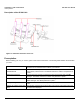
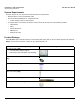
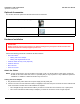
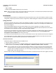
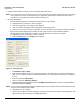
Table Of Contents
- Introduction
- Installation and Initialization
- Managing the Access Point
- Basic Configuration for an Enterprise
- Access Point Features
- Using Web Interface to Manage the Access Point
- Using SNMP Interface to Manage the Access Point
- Using CLI to Manage the Access Point
- Global Configuration Mode
- General Notes
- Configuring the AP using CLI Commands
- Command Line Interface Mode Overview
- User Exec Mode
- Privileged Exec Mode
- Show Command Tree Structure Command
- Show VLAN Command
- Show MAC ACL Command
- Show RADIUS Server Table Command
- Show RADIUS Supported Profile Table Command
- Show Security Wireless Config Table Command
- Show QoS Profile and Policy Command
- Show QoS EDCA Command
- Show Wireless Properties Command
- Show 11n Wireless Properties Command
- Wireless VAP Command
- Ethernet Interface Command
- Network Configuration Command
- Advaned Filter and Global Filter Command
- TCP-UDP and Static MAC Address Table Commands
- Protocl Filter, Filter Type and Filter Control Table Command
- Access Control and HTTP, Telnet and TFTP Commands
- SNMP Read, Read-Write Password and Trap Host Table Command
- Country Code and Management Commands
- System Information Command
- System Inventory Management Command
- Event Logand ICMP Commands
- IP ARP Statistics and SNTP Command
- Syslog configuration and RADIUS Client Authentication Table Commands
- RADIUS Client Access Command
- Interface Statistics Command
- Wireless Station Statistics Command
- IP Address, Subnet Mask and Gateway Command
- Scalar Objects Commands
- Table Entries Commands
- Table Entry Deletion Command
- Table Entry Edition Command
- VAP Table Commands
- Troubleshooting
- ASCII Character Chart
- Bootloader CLI
- Specifications
- Technical Services and Support
- Statement of Warranty

Installation and Initialization AP-800 User Guide
Hardware Installation
16
• The AP must be protected from exposure, and the environmental conditions must be within those specified in the
product datasheet that can be found at http://www.proxim.com/products/
• The AP-800 uses +5V/3A power adapter.
• Note that the AP-800 has been certified under UL Standard 2043 and can be installed in the plenum. In an office
building, plenum is the space between the structural ceiling and the tile ceiling that is provided to help air circulate.
Many companies also use the plenum to house communication equipment and cables. These products and cables
must comply with certain safety requirements, such as Underwriter Labs (UL) and Standard 2043: “Standards for Fire
Test for Heat and Visible Smoke Release for Direct Products and Their Accessories installed in Air-Handling Spaces”.
NOTE: When installed in a plenum, the AP must use PoE.
Once you have chosen a final location for your unit, the following are the mounting options are available:
• Wall Mounting
• Ceiling Mounting
Wall Mounting
Follow these steps to mount the unit on a wall:
1. If the unit’s power supply is plugged in, unplug it.
2. Put the mounting plate up to the wall so that the embossed letter “L” is on the top. If the plate is correctly oriented, the
circular tab that is vertically aligned with the square hole should be on top.
3. Fasten the mounting plate with two screws through the circular holes of the plate. Depending on the type of wall, you
may need to use the fasteners.
4. Holding the unit so that the connectors on the rear, align the holes on the bottom of the unit with the two tabs on the
mounting plate. Press the unit down so it is flush with the plate.
5. Carefully slide the unit to the up until the tabs snap securely on to the narrow holes of the unit. if the unit is mounted
correctly, no portion of the mounting plate should protrude from any of the sides of the unit.
Ceiling Mounting
Follow these steps to mount the unit to a ceiling:
1. If the unit’s power supply is plugged in, unplug it.
2. Snap the rectangular tabs on the back of the mounting plate onto a ceiling T-bar. You may need to slightly rotate the
plate until it securely snaps onto the T-bar.
3. Fasten the mounting plate to the ceiling tile with two screws through the circular holes of the plate.
4. Position so that the embossed letter “L” on the mounting plate is facing up. Hold the unit so that the connectors on the
rear, align the two holes on the bottom of the unit with the two tabs on the mounting plate. Press the unit up so it is
flush with the plate.
5. Carefully slide the unit to the “L” direction until the tabs snap securely onto the narrow holes of the unit. If the unit is
mounted correctly, no portion of the mounting plate should protrude from any of the sides of the unit.
Power on the Unit
The AP can be powered by a power supply (just plug the power cord of the power supply into an AC power outlet), or by
Gigabit Ethernet PoE.
When power is applied to the Access Point, you will observe that Power LED lights up Green.
Connect the AP-800 LAN port to a stand-alone PC using Ethernet cable, or to a network hub or switch. You can monitor
the Ethernet LEDs on the top of the Access Point. The color of the Ethernet LEDs will inform about the speed of the
Ethernet traffic:
• GREEN: 1000 Mbps