
User guide
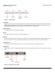
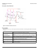
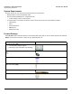
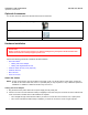
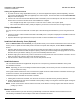
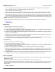
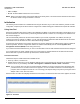
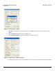
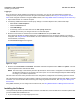
Table Of Contents
- Introduction
- Installation and Initialization
- Managing the Access Point
- Basic Configuration for an Enterprise
- Access Point Features
- Using Web Interface to Manage the Access Point
- Using SNMP Interface to Manage the Access Point
- Using CLI to Manage the Access Point
- Global Configuration Mode
- General Notes
- Configuring the AP using CLI Commands
- Command Line Interface Mode Overview
- User Exec Mode
- Privileged Exec Mode
- Show Command Tree Structure Command
- Show VLAN Command
- Show MAC ACL Command
- Show RADIUS Server Table Command
- Show RADIUS Supported Profile Table Command
- Show Security Wireless Config Table Command
- Show QoS Profile and Policy Command
- Show QoS EDCA Command
- Show Wireless Properties Command
- Show 11n Wireless Properties Command
- Wireless VAP Command
- Ethernet Interface Command
- Network Configuration Command
- Advaned Filter and Global Filter Command
- TCP-UDP and Static MAC Address Table Commands
- Protocl Filter, Filter Type and Filter Control Table Command
- Access Control and HTTP, Telnet and TFTP Commands
- SNMP Read, Read-Write Password and Trap Host Table Command
- Country Code and Management Commands
- System Information Command
- System Inventory Management Command
- Event Logand ICMP Commands
- IP ARP Statistics and SNTP Command
- Syslog configuration and RADIUS Client Authentication Table Commands
- RADIUS Client Access Command
- Interface Statistics Command
- Wireless Station Statistics Command
- IP Address, Subnet Mask and Gateway Command
- Scalar Objects Commands
- Table Entries Commands
- Table Entry Deletion Command
- Table Entry Edition Command
- VAP Table Commands
- Troubleshooting
- ASCII Character Chart
- Bootloader CLI
- Specifications
- Technical Services and Support
- Statement of Warranty

Installation and Initialization AP-800 User Guide
Hardware Installation
15
Cabling with Gigabit Ethernet PoE
1. To power the device using Gigabit Ethernet PoE, you must use Gigabit PoE injector (ordered separately). Connect
one end of a CAT6 Ethernet cable (not supplied) to the unit’s LAN port. Connect the other end to the Data and Power
Out port of the PoE Injector.
2. Connect one end of the second CAT6 Ethernet cable to the Data In port of the DC Injector. The other end of the cable
should not be connected to another device until installation is complete:
• Use a straight-through cable if you intend to connect the unit to a switch, hub or patch panel.
• Use a cross-over Ethernet cable (CAT6) or adapter if you intend to connect the unit to a single computer.
Using a Console Port
You may connect your Access Point with a console port. Follow the steps provided below if you are using the Console
port:
1. Connect a nine-pin, male-to-female serial cable to the COM port on a computer or laptop and to the DB9 connector of
the Access Point.
2. Open the Microsoft’s HyperTerminal to set up the AP-800. For more information refer Initialization.
Install the Cable Security Cover (Optional)
When the RS-232 cable is not connected, you may install a security cover to deter unauthorized access to the unit. The
security cover is a plastic enclosure that prevents access to the power and LAN ports, and the Reset and Reload
buttons.
1. Open the split end of the security cover just enough to slide the power cable (if you are not using Gigabit Ethernet
PoE) and the CAT 6 Ethernet cable through the opening until they fit inside the straight clamping portion of the cover.
Exercise care as you slide the cable (s) so you do not accidentally break the cover.
2. Slide the hinging end of the security cover into the hole on the rear panel of the unit to the left of connectors. Once in
place, pivot the cover to bring it close to the rear panel of the unit.
3. Use two screws to fasten the security cover on to the rear panel of the unit.
Install the Antenna
The omni-directional antennas supplied with the product do not require any professional installation as they have
non-standard connectors.
NOTE: Optionally, you can use the Range extended Antenna (REA). This accessory also has non-standard connectors,
and can install them easily.
If the regular outdoor antennas are used, connected via a pigtail conversion cable that offers a standard connector type
for antenna connection, then professional installation is required.
Follow these steps to assemble the antennas to AP-800:
1. Hand-tighten the antennas clockwise, onto the outer connectors of AP-800 until they are firmly attached.
2. Position the antennas as close to the horizontal surface (ceiling or wall), so as to get the maximum signal coverage of
the omni-directional antenna.
NOTE: Proxim recommends to aim the antenna horizontal, as the wireless coverage angle is wider with the antenna
pointing up or down.
Mount the Unit
Proxim recommends that you have site survey professionally conducted to determine the best location for the AP.
The following considerations must be kept in mind when the AP-800 is mounted.