
Installation guide
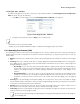

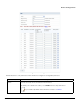

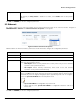
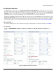
Table Of Contents
- Preface
- Introduction
- Management and Monitoring Capabilities
- Device Initialization
- Basic Configuration
- Device Configuration
- Device Management
- Device Monitoring
- Troubleshooting
- Frequency Domains and Channels
- Bootloader CLI and Scan Tool
- ASCII Character Chart
- Frequently Asked Questions (FAQs)
- Glossary
- Abbreviations
- Statement of Warranty
- Technical Services and Support
Device Configuration
ORiNOCO® 802.11n Access Points - Software Management Guide 33
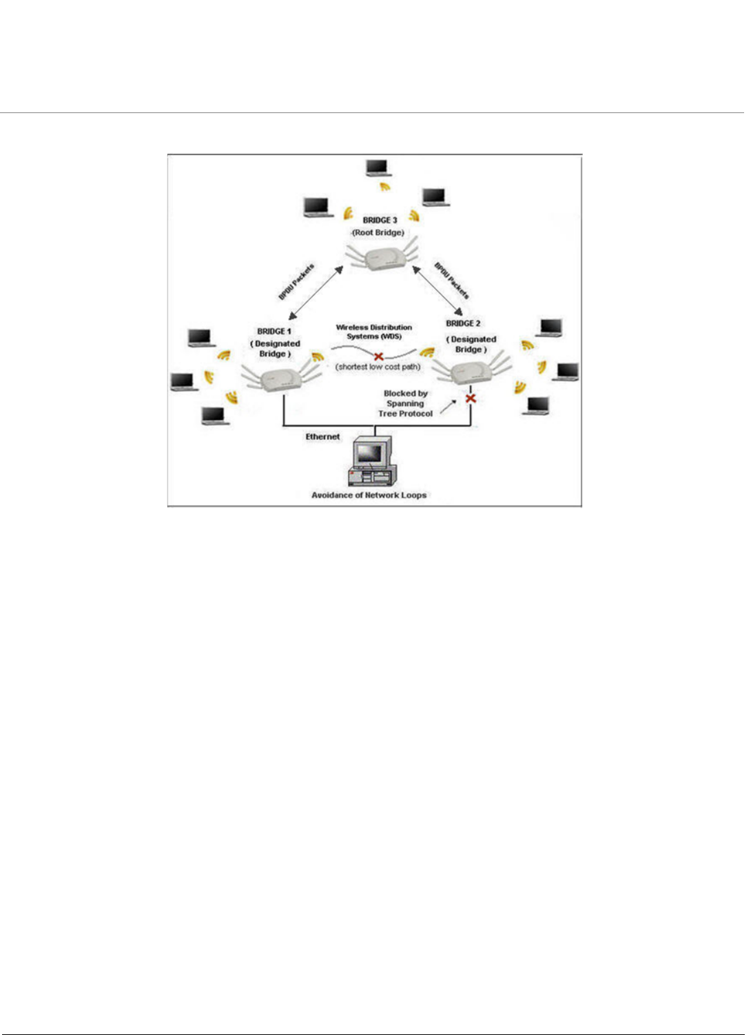
Example: Let us consider a network with three Bridges (Bridge 1, Bridge 2 and Bridge 3)
Figure 5-6 STP Topology
• Bridge 1 and Bridge 2 are connected via both Wireless and Ethernet interface, while Bridge 3 is connected to Bridge 1
and Bridge 2 only via Wireless interface.
• To avoid a network loop between Bridge 1 and Bridge 2, the STP feature should be enabled on all the devices.
• Once the STP feature is enabled, Bridge 1, Bridge 2 and Bridge 3 change from Disable state to Listening state and
start exchanging the BPDU packets. Bridge 3, having the highest priority and smallest MAC Address, acts as the Root
Bridge, and Bridge 1 and Bridge 2 act as Designated Bridges.
• The Designated Bridges (Bridge 1 and Bridge 2) then determine the shortest low cost path via root port, to forward
the data from bridge 1 to bridge 2, on a loop- free bridged network.
• Bridge 1 and Bridge 2 switch from Listening state to Learning state where they update the learn tables and enable
the shortest low cost path determined.
• The STP enabled Bridge 2 then changes from Learning state to Blocking state and blocks all the longest high cost
paths, near both wireless and ethernet interfaces.
• Bridge 1 finally changes from Learning state to Forwarding state and forwards the data packet to Bridge 2 through
the shortest low cost path (via the root port of Bridge 3) enabled, avoiding loops on the network.
Navigate to CONFIGURATION > Network > STP. The Network STP Configuration screen appears.