ORiNOCO® 802.
Copyright © 2012 Proxim Wireless Corporation, Milpitas, CA. All rights reserved. Covered by one or more of the following U.S. patents: 5,231,634; 5,875,179; 6,006,090; 5,809,060; 6,075,812; 5,077,753. This guide and the software described herein are copyrighted with all rights reserved. No part of this publication may be reproduced, transmitted, transcribed, stored in a retrieval system, or translated into any language in any form by any means without the written permission of Proxim Wireless Corporation.
Contents Preface . . . . . . . . . . . . . . . . . . . . . . . . . . . . . . . . . . . . . . . . . . . . . . . . . . . . . . . . . . . . . . . . . . . . . . 5 1 Introduction . . . . . . . . . . . . . . . . . . . . . . . . . . . . . . . . . . . . . . . . . . . . . . . . . . . . . . . . . . . . . . . . . . 7 Introduction to Wireless Networking . . . . . . . . . . . . . . . . . . . . . . . . . . . . . . . . . . . . . . . . . . . . . . . . . . . . . . . 7 About ORiNOCO® 802.11n Access Points . . . . . . . . .
Station Statistics . . . . . . . . . . . . . . . . . . . . . . . . . . . . . . . . . . . . . . . . . . . . . . . . . . . . . . . . . . . . . . . . . . . . 116 Rogue Scan Statistics . . . . . . . . . . . . . . . . . . . . . . . . . . . . . . . . . . . . . . . . . . . . . . . . . . . . . . . . . . . . . . . . . 118 Bridge . . . . . . . . . . . . . . . . . . . . . . . . . . . . . . . . . . . . . . . . . . . . . . . . . . . . . . . . . . . . . . . . . . . . . . . . . . . . 120 Network Layer . . . . . . . . . .
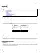
Preface Preface This chapter contains the information on the following: • About this Guide • Products Covered • Audience • Prerequisites • Documentation Conventions • Related Documents About this Guide This guide gives a jump-start working knowledge on the ORiNOCO® 802.11n Access Points. It explains the step-by-step procedure to configure, manage and monitor the device by using Web Interface. Products Covered Tabulated below are the ORiNOCO® 802.
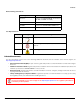
Preface Device Naming Conventions Naming Convention Description AP Device Refers to any ORiNOCO® 802.11n AP device (AP-800 / AP-8000 / AP-8100) AP-800 Refers to the ORiNOCO® AP-800 device AP-8000 Refers to the ORiNOCO® AP-8000 device AP-8100 Refers to the ORiNOCO® AP-8100 device Icon Representation Name Image Meaning Note A special instruction that draws the attention of the user. Important A note of significant importance, that a user should be aware of.
1 Introduction This chapter contains information on the following: • Introduction to Wireless Networking • About ORiNOCO® 802.11n Access Points — Salient Features — Applications • Multiple-Input-Multiple-Output 1.1 Introduction to Wireless Networking Wireless Networking refers to the technology that enables two or more computers to communicate by using standard network protocols, but without network cabling, generally referred to Wireless LAN (WLAN).
Introduction 1.2.1 Salient Features • Easy operation and installation • Industry-leading throughput in 802.11b/g/n and 802.11a/n modes in 2.4GHz and 5GHz respectively. • Highest throughput with single radio rates of 150 - 170 Mbps and dual radio rates of 250 - 300 Mbps. • Advanced WPA/WPA2 support for enterprise-grade security. • Wi-Fi certified to interoperate with any Wi-Fi certified client access product. • Provides wall mounting or ceiling option for flexible device installation.
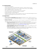
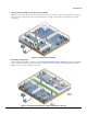
Introduction 4. Seamless client roaming for both data and voice (VoIP): Multiple wireless clients can connect to a single AP Device, or they can move between multiple AP Devices located within the same vicinity. As wireless devices move from one coverage cell to another, they maintain the network connectivity. Figure 1-2 Seamless Client Roaming 5. Extended Coverage Areas: Proxim’s high capacity, 802.
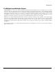
Introduction 1.3 Multiple-Input-Multiple-Output ORiNOCO® 802.11n AP Devices support Multiple-Input-Multiple-Output (MIMO) antenna technology that uses multiple antennas at both the transmitting end and receiving end to improve communication performance. The underlying technology of these access point radio(s) are based on a combination of MIMO and OFDM (Orthogonal Frequency Division Multiplexing). MIMO-OFDM combination radios solve interference, fading and multipath problems.
Management and Monitoring Capabilities 2 This chapter contains information on the following: • Managing and Monitoring Capabilities — Web (HTTP/HTTPS) Interface — Command Line Interface (CLI) (Terminal Emulators) — Simple Network Management Protocol (SNMP)v1/v2c/v3 — ProximVision ES (PVES) 2.1 Managing and Monitoring Capabilities A Network Administrator can use the following interfaces to configure, manage and monitor the device.
Management and Monitoring Capabilities Port COM1 (default) Baud Rate 115200 Data 8-bit Parity None Stop 1-bit Flow Control None : • If you are using Windows 7 operating system, then use Terminal Emulator programs for serial connection. • HyperTerminal Serial Connection is not applicable to AP-8100, as it does not have a serial port. However, you can access the CLI via your LAN (switch, hub and so on), internet, or with an ethernet cable connected directly to your computer’s ethernet Port. 2.1.
Management and Monitoring Capabilities The Enterprise MIB defines the read and read-write objects that can be viewed or configured by using SNMP. These objects correspond to most of the settings and statistics that are available with the other management interfaces. All Read-Only (RO) and Read-Write (RW) parameters supported by the IEEE802dot11-MIB are as tabulated below. S.No.
Management and Monitoring Capabilities : For details on configuring the device through the SNMP Interface, please refer to the ORiNOCO® 802.11n Access Points - Reference Guide. 2.1.4 ProximVision ES (PVES) ProximVision ES (commonly known as PVES) is Proxim’s Network Management System that helps to manage and administer your wireless network effectively and efficiently.
Device Initialization 3 This chapter contains information on the following: • Initialization — ScanTool — Initialize the Device by using ScanTool — Modifying the IP Address • Logging onto the Web Interface • Home Page — Commit — Reboot 3.1 Initialization You can initialize the device either through CLI commands, Web Interface or an SNMP Interface. • To initialize the device by using CLI commands, connect a serial RS-232 cable to the Serial Port of the device. : AP-8100 does not have a serial port.
Device Initialization : • The user may need to disable Windows Firewall for ScanTool to function or to detect the radio. • ScanTool works only for the Proxim products. 3.1.2 Initialize the Device by using ScanTool To scan and locate the devices on a network by using ScanTool, do the following: 1. Power on, or reset the device 2. To download Proxim’s ScanTool, log on to Proxim’s support site at http://support.proxim.com and search for ScanTool with (Answer ID 1735).
Device Initialization 7. Click Select Adapter, to change the adapter settings. 8. Locate the MAC address of the device you want to initialize from the Scan List and click Web Config to logon to the Web Interface. See Logging onto the Web Interface : • If device does not appear in the Scan List, click Rescan in the Scan List to update. If the device still does not appear in the list, see Troubleshooting.
Device Initialization 3.1.3.2 Assigning the IP Address Dynamically : Before setting the IP Address Type as Dynamic, ensure there is a DHCP server on the network. To change the IP Address type from Static to Dynamic, follow these steps: 1. Select the IP Address Type as Dynamic. The IP Address, Subnet Mask and the Gateway IP Address fields get disabled. 2. Enter the SNMP Read/Write password in the Read/Write Password field. By default, it is public. 3. Click OK to save the changes. 4.
Device Initialization • If using Internet Explorer, and you enter wrong password consecutively for three times, the HTTP session will get disconnected. If case of other browsers, the login screen will reset until you enter the correct password. • In the Internet Explorer, to get best results, navigate to Tools > Internet Options > General. Click Settings in the Browsing History and select “Every visit to the webpage”. Figure 3-4 Internet Explorer Settings ORiNOCO® 802.
Device Initialization 3.3 Home Page Upon successful login, the Home Page screen appears. Figure 3-5 System Summary The home page contains the following information: 1. Device Description: The device description is displayed on the top-right corner of the home page. It displays the system-name, device type, regulatory domain, latest software version supported and firmware version loaded on the device. 2.
Device Initialization Before applying commit, the system displays a confirmation message, as shown in the following figure: Figure 3-6 Commit Click OK, if you wish to commit the changed parameters. On successful Commit operation, the following screen appears: Figure 3-7 Commit Status If the configured parameters requires reboot, on committing the following screen appears. Figure 3-8 Commit Status with Reboot Message 3.3.
Device Initialization Figure 3-9 Reboot Click OK, if you want to reboot the device. : • Every parameter requiring REBOOT upon its configuration, is marked with a red asterisk and it is recommended to reboot the device immediately after modifying a rebootable parameter. • If the device does not reboot and redirect you to the HOME Page within 2 minutes, then we recommended you to check the network connectivity and try accessing the page later. ORiNOCO® 802.
4 Basic Configuration This chapter contains information on the following: • Basic Configuration • Factory Default Configuration • Parameters requiring Reboot : All the interface (radio) 2 parameters discussed in this chapter are applicable only to a dual-radio device. 4.1 Basic Configuration Tabulated below are the parameters to be configured to operate the AP device at a basic level: Parameter IP Address Description If you have DHCP Server on your network, then set the Address Type as Dynamic.
Basic Configuration SSID Default SSID set on both the radios, is as tabulated below: Device Type SSID Radio 1 Radio 2 AP-800 My Wireless Network 1_1 Not Applicable AP-8000 My Wireless Network 1_1 My Wireless Network 2_1 AP-8100 My Wireless Network 1_1 My Wireless Network 2_1 For details on how to change SSID, refer to Virtual Access Point (VAP) By default, the security is set to None.
Basic Configuration Operational Mode Current Bandwidth Device Type Operational Mode (Supported Frequency Band) Radio 1 Radio 2 AP-800 802.11g/n (2.4 GHz) Not Applicable AP-8000 802.11a/n (5 GHz) 802.11g/n (2.4 GHz) AP-8100 802.11a/n (5 GHz) 802.11g/n (2.
Basic Configuration Parameter(s) Web Page(s) Address Type IP Address Subnet Mask CONFIGURATION - > Network - > IP Configuration Gateway IP Address DNS Primary IP and Secondary IP Address Radio Mode Country Code CONFIGURATION - > Wireless - > Interface 1/ Interface 2 - > Properties Operational Mode Current Bandwidth Frequency Extension CONFIGURATION - > Wireless - > Interface 1/ Interface 2 - > 11n Properties Update Firmware (HTTP / TFTP) MANAGEMENT - > File Management - > Update Firmware Update C
Device Configuration 5 This chapter explains the step-by-step procedure to configure the following features on the device, by using Web Interface: • System • Network — IP Configuration — Link Integrity — Spanning Tree Protocol (STP) • Ethernet • Wireless Interface — Interface 1 — Properties — 11n Properties — Virtual Access Point (VAP) — Interface 2 • Security — Wireless Security — RADIUS — MAC Access Control • Quality of Service (QoS) — Enhanced Distributed Channel Access (EDCA) — 802.
Device Configuration : All the interface (radio) 2 parameters discussed in this chapter are applicable only to a dual-radio device. 5.1 System The System feature enables you to configure system specific information. Navigate to CONFIGURATION > System. The System screen appears. Figure 5-1 System Tabulated below are ‘System’ parameters and the method to configure the configurable parameters: Parameter Description System Name Specifies the name assigned to the device.
Device Configuration Figure 5-3 Network IP Configuration Tabulated below are ‘Network IP’ parameters and the method to configure the configurable parameters: Parameter Address Type Description By default this parameter is set to Dynamic. When set to dynamic, the device will obtain IP settings from a network Dynamic Host Configuration Protocol (DHCP) server automatically during the boot-up.
Device Configuration Primary IP Address Specifies the IP Address of the Primary DNS Server. When the address type is set to Dynamic, this parameter is read-only and displays the DNS Primary IP Address obtained from the DHCP server. If the Address Type is set to Static then you will have to manually enter the IP Address in the Primary IP Address box. Secondary IP Address Specifies the IP Address of the Secondary DNS Server.
Device Configuration Tabulated below are ‘Link Integrity’ parameters and the method to configure the configurable parameters: Parameter Status Description Specifies the status of the link integrity feature on the device. By default, it is disabled. To enable, select Enable from the drop down menu. Polling Time Specifies the time interval, during which the device will check the link integrity with its configured server(s) by sending the ICMP echo probes. By default, the Polling Time taken is 30 seconds.
Device Configuration Link Integrity Table - Add Row To enable link integrity on the AP device, atleast one entry should be added to the Link Integrity Server Configuration Table. To add an entry, do the following: 1. Click Add in the link integrity screen, the Link Integrity Table - Add Row screen appears: Figure 5-5 Link Integrity Table - Add Row 2. Configure all the parameters and click Add, to save the added entry. : • A maximum of five servers can be added.
Device Configuration Example: Let us consider a network with three Bridges (Bridge 1, Bridge 2 and Bridge 3) Figure 5-6 STP Topology • Bridge 1 and Bridge 2 are connected via both Wireless and Ethernet interface, while Bridge 3 is connected to Bridge 1 and Bridge 2 only via Wireless interface. • To avoid a network loop between Bridge 1 and Bridge 2, the STP feature should be enabled on all the devices.
Device Configuration Figure 5-7 STP Configuration Tabulated below are ‘STP’ parameters and the method to configure the configurable parameters: Parameter Status Description Specifies the status of the STP feature on the AP device. By default, STP is disabled. To enable, select Enable from the drop down menu. : If you enable STP, disable 'Filter STP Frames' in Filters. See Filters. ORiNOCO® 802.
Device Configuration Bridge Priority Specifies the priority assigned to a bridge. By default, a bridge is assigned with a priority of 4096. To configure, enter a value between 0 - 61440 (as multiples of 4096). : Bridge assigned with the lowest value gets the highest priority, and is selected as Root Bridge. Maximum Age Specifies the maximum time period for an AP device to hold the BPDU packet before discarding it. By default, it is 20 seconds.
Device Configuration Entry Status Specifies the status of the selected port. By default, the Entry Status is disabled. To enable, select Enable from the drop down menu. Click OK and COMMIT, to save the configured parameters. 5.3 Ethernet This feature enables you to view and configure the speed and transmission mode of the ethernet interface. Navigate to CONFIGURATION > Ethernet. The Ethernet Interface Properties screen appears.
Device Configuration 5.4 Wireless Interface The Wireless feature enables you to use Multiple Input Multiple Output (MIMO) technology, that uses several antennas to transfer multiple data streams thus enabling more data to be transferred in the same period of time. The wireless architecture is based on the cellular architecture where the systems are divided into cells, and each cell is called Basic Service Set (BSS).
Device Configuration Tabulated below are ‘Wireless Interface’ parameters and the method to configure the configurable parameters: Parameter Radio Status Description Specifies the status of the radio on the AP device. By default, it is enabled. To disable, select Disable from the drop down menu. If the radio status is disabled, the interface gets shutdown. Radio Mode This parameter enables you to set the radio mode of the AP device. The available radio mode is AP.
Device Configuration Current Bandwidth Specifies the frequency band used to transmit the wireless data. The available bandwidths are 20 MHz and 40 MHz. By default, the AP device operates in 40MHz. To set the bandwidth for the wireless data transmission, select a value from the drop down menu. : Set the current bandwidth to 20 MHz, to enable the legacy operational modes of 802.11a or 802.11g.
Device Configuration TPC (Transmit Power Control) Back-off The AP device transmits maximum output power, as per the selected frequency and country (regulatory domain). With TPC Back-off, you can adjust the output power of the AP device to a lower level in order to reduce the interference with the neighboring devices or to use a higher gain antenna without violating the maximum radiated output power allowed for your regulatory domain. By default, it is set to 0 dBm.
Device Configuration Cell Size WDS Cell Size Functionality For a WDS link (See WDS (Wireless Distribution System) Mode), when the cell size is set from Large to Micro, Mini, Small or Medium, the transmit power is retained to the maximum value. Tabulated below are the details that explain the WDS Cell Size Functionality for different Cell Sizes.
Device Configuration WDS Optimization Mode : If, a. WDS Optimization Mode is enabled, b. Current Bandwidth is set to 40 MHz and c. The extension channel is busy then, the AP device operates with a channel bandwidth of 40 Mhz only (Dynamic 20/40 mode is not applicable here). The same is applicable on the other VAPs enabled in AP mode. DTIM (Delivery Traffic Indication Map) Specifies the number of beacon frames that can be transmitted before another DTIM is transmitted.
Device Configuration Rogue Scan Period This parameter is enabled when Rogue Scan Status is set to All channel Scan. This parameter specifies the time period for which, the AP device scans each available channel to detect every wireless device in its vicinity. By default, it is 250ms. To configure, enter the time period value between 100- 1000ms Click OK and COMMIT, to save the configured parameters.
Device Configuration AMPDU Max Num Frames Specifies the maximum number of frames that are aggregated and transmitted as a single Protocol Service Data Unit (PSDU) by the physical layer. By default, the AMPDU Max Num Frames is 64. To configure, enter a value ranging from 2 to 64 frames. AMPDU Max FrameSize Specifies the maximum AMPDU frame size (in bytes) that can be transmitted. By default, the AMPDU Max FrameSize taken is 65535 bytes. To configure, enter the frame size ranging from 1k to 64k bytes.
Device Configuration Each wireless interface supports eight VAPs. By default, the first VAP on an interface is always enabled. The AP device supports two VAP types: A. AP (Access Point) Mode B. WDS (Wireless Distribution System) Mode A. AP Mode The VAP enabled in AP mode will support the standard AP functionality. To configure a VAP in AP mode, select the radio button against the desired VAP and click Edit (See Wireless Interface -1 VAP).
Device Configuration SSID Specifies the unique network name used to identify a wireless network. To change the wireless network name, enter a new name in the SSID box with a maximum of 31 characters. BSSID Specifies a read-only parameter and it displays the VAP’s MAC Address. Broadcast SSID The continuous announcement of the SSID in the beacons by VAP is called Broadcast SSID. The SSID is also broadcasted in probe response frames.
Device Configuration VLAN ID Specifies the VLAN ID for the wireless VAP. By default, the VLAN ID is set to -1 which means that VLAN tag is disabled. To enable VLAN tag, enter a value ranging from 1 to 4094 in the VLAN ID box. VLAN Priority Specifies the VLAN priority for the Wireless VAP. By default the value is set to 0. To configure this parameter, enter a value ranging from 0 to 7 in the VLAN Priority box. : To configure the VLAN ID and VLAN Priority for a VAP, VLAN status should be enabled.
Device Configuration Max Stations This parameter allows you to restrict the maximum number of wireless clients that can be associated with each VAP. A maximum of 128 wireless clients can be connected per radio. By default, the Max Stations value taken for each VAP is 64. To configure, enter a value ranging from 1 to 128. : A VAP (already connected to the maximum number of wireless clients) responds to a probe request from a new client, with a probe response.
Device Configuration Figure 5-13 Wireless Distribution System Lets say, Access Point 1 of BSS1 wants to communicate with Access Point 2 of the BSS2 in its vicinity. In such a scenario, both the Access Points 1 and 2, register each other's MAC address. Once registered, a WDS link is established between BSS 1 and BSS 2.
Device Configuration Figure 5-14 (a) VAP in WDS - Legacy Mode Figure 5-14 4 (b) VAP in WDS - 11n Mode Tabulated below are the ‘WDS Mode’ parameters and the method to configure the configurable parameters: Parameter Status Description Specifies the status of the VAP. By default, it is enabled. To disable a VAP, select Disable from the drop down menu. Type Specifies the type of the VAP configured. (VAP Type may be in AP, WDS-Legacy or WDS END-A/END-B).
Device Configuration : When WDS link is DOWN, the following behavior is expected: • If WDS-ENDA and VAP-AP are on same radio, then the VAP-AP transmits the beacons. • All the VAPs on the same interface (radio) as WDS-END B, stop transmitting the beacons. • The VAPs on an interface (radio) other than WDS-END B, transmit the beacons. Click OK and COMMIT, to save the configured changes. : • All the eight VAPs on an interface, can be enabled in WDS mode.
Device Configuration • 802.1x Authentication 802.1x provides an authentication framework for wireless LANs, allowing a user to be authenticated by a central authority. 802.1x uses an existing protocol, the Extensible Authentication Protocol (EAP, RFC 2284), that works on Ethernet, Token Ring, or wireless LANs for message exchange during the authentication process. In a wireless LAN with 802.1x, a user (known as the Supplicant) requests access to an Access Point (known as the Authenticator).
Device Configuration 5.5.1.1 Create a New Security Profile To add a new security profile, click Add in the Wireless Security Configuration screen. The Wireless Security Add Row screen appears. Figure 5-16 Add Wireless Security Profile Tabulated below are the ‘Wireless Security Profile’ parameters and the method to configure the configurable parameters: Parameter Description Profile Name Specifies the name of the Security Profile that is being created. To configure, enter the desired Profile Name.
Device Configuration Authentication Mode Parameter Key Description This parameter allows you to configure the WEP key for the wireless security. Enter a WEP Key in the Key box. – For 64-bit encryption, an encryption key is 10 hexadecimal characters (0-9 and A-F) or 5 ASCII characters. See ASCII Character Chart. – For 128-bit encryption, an encryption key is 26 hexadecimal characters or 13 ASCII characters. – For 152-bit encryption, an encryption key is 32 hexadecimal characters or 16 ASCII characters.
Device Configuration Authentication Mode Parameter Description Encryption Type Specifies the Encryption Type. By default, it is taken as WPA-TKIP. To configure, select either WPA-TKIP, WPA2-AES or WPA-WPA2AES-TKIP from the drop down menu. :When the Encryption Type is set to WPA-WPA2AES-TKIP, the device supports clients with the encryption type of either WPA-TKIP or WPA2-AES. PSK Specifies the pass phrase that derives the PSK.
Device Configuration Authentication Mode Parameter Encryption Type Description Specifies the Encryption Type. By default, it is taken as WEP. To configure, enter the Encryption Type as either WEP, WPA-TKIP, WPA2-AES or WPA-WPA2AES-TKIP from the drop down menu. :When the Encryption Type is set to WPA-WPA2AES-TKIP, the device supports clients with the encryption type of either WPA-TKIP or WPA2-AES.
Device Configuration Configure the following parameters: Parameter Description Profile Name Specifies the name of the Security Profile that is being created. To configure, enter the desired Profile Name. Authentication Mode Specifies the security mode for the wireless network. The Auth Mode may vary between None, WEP, PSK, 802.1x. (See Create a New Security Profile) Entry Status Specifies the status of the security profile selected. By default, it is enabled.
Device Configuration • Acct-Interim-Interval: Specifies the attribute obtained during the Authentication process and used for determining the time interval for sending Accounting Update messages. : If this attribute is not obtained from the RADIUS Server, the AP device uses default value of 300 seconds for updating the accounting messages. 5.5.2.2 Accounting Attributes • Acct-Status-Type: Specifies whether this Accounting-Request marks the beginning of the user service (Start) or the end (Stop).
Device Configuration Tabulated below are the ‘RADIUS Server Profile’ parameters and the method to configure the configurable parameters: Parameter Description Profile Name Specifies the RADIUS profile name which is used to identify a set of four RADIUS servers configured one per Accounting, Authentication, Secondary Accounting and Secondary Authentication. Max Re Transmissions Specifies the maximum number of times an authentication request may be retransmitted. By default, it is set to 3.
Device Configuration 5.5.3 MAC Access Control The MAC Access Control feature of AP device allows only the authorized wireless clients to access the network. MAC Authentication is supported only on the wireless interface. Navigate to CONFIGURATION > Security > MAC ACL. The MAC Access Control screen appears. Figure 5-22 MAC Access Control Configure the following parameters: Parameter Operation Type Description Specifies the two types of operations, Allow or Deny.
Device Configuration Configure the following parameters: Parameter Description MAC Address Specifies the MAC Address of a wireless client being added. To configure, enter the MAC address of the wireless client. Comment Specifies any comment to be entered in the Comment box. Entry Status Specifies the entry status of the added wireless client. By default, the Entry Status for a wireless client is enabled. To configure, select Enable or Disable from the drop down menu.
Device Configuration Station EDCA Table and AP EDCA Table This feature allows the user to configure the EDCA parameters for the wireless client (Station) and the AP device. The EDCA parameter set provides information needed by the wireless clients for proper QoS operation during the wireless contention period. These parameters are used by the QoS enabled AP device to establish policy, to change policies when accepting new clients or new traffic, or to adapt to changes in the offered load.
Device Configuration Figure 5-25 STA EDCA Table (left) /AP EDCA Table (right) - Edit Entries Tabulated below are the ‘QoS EDCA’ parameters and the method to configure the configurable parameters: Parameter Access Category Description Specifies a label for the common set of EDCA parameters that are used by a QoS STA/AP to contend for the channel in order to transmit MSDUs with certain priorities.
Device Configuration Access Category Default EDCA Parameters for Station Default EDCA Parameters for AP CW Min CW Max AIFS Tx OP (Unsigned Integer) CW Min CW Max AIFS Tx OP (Unsigned Integer) Background 15 1023 7 0 15 1023 7 0 Best Effort 15 1023 3 0 15 63 3 0 Video 7 15 2 3.008 ms 7 15 1 3.008 ms Voice 3 7 2 1.504 ms 3 7 1 1.504 ms CW Min Specifies the minimum value for Contention Window (CW) for the wireless QoS EDCA profile.
Device Configuration Figure 5-26 802.1d To IP DSCP Mapping Table Tabulated below are the ‘QoS 802.1d and IP DSCP (Differentiated Services Code Point) (for layer 3 policies)’ parameters and the method to configure the configurable parameters: Parameter Description 802.1d to IP DSCP Index Specifies a read-only parameter which indicates the IP DSCP index corresponding to 802.1d priority. Lower Limit and Upper Limit Specifies the IP DSCP range (lower and Upper limit) for each 802.1d priority.
Device Configuration Tabulated below are the ‘QoS 802.1d and 802.1p (for layer 2 policies)’ parameters and the method to configure the configurable parameters: Parameter Description 802.1d Priority Specifies a read-only parameter which represents the 802.1d priority. 802.1p Priority Specifies the 802.1p priority mapped to the corresponding 802.1d priority. To configure, enter the 802.1p Priority, for the corresponding 802.1d priority, in the range of 0 to 7.
Device Configuration Figure 5-29 QoS Policy Tabulated below are the ‘QoS Policy’ parameters and the method to configure the configurable parameters: Parameter Description Policy Name Specifies a read-only parameter which represents the QoS Policy Name. Policy Type Specifies a read-only parameter which represents the QoS Policy Type. The available Policy types are: – Inbound Layer 2: Represents inbound traffic direction with layer 2 traffic type.
Device Configuration 5.7 Virtual Local Area Network (VLAN) Virtual Local Area Network (VLAN) is the logical grouping of network hosts. The VLAN members appear (to clients) to be on the same physical segment as others, no matter where they are available on the logical LAN or WAN segment. They simplify traffic flow between clients, and their frequently used or restricted resources. In a BSS, clients can be segmented into wireless sub-networks via SSID and VLAN assignment.
Device Configuration Tabulated below are the ‘VLAN’ parameters and the method to configure the configurable parameters: Parameter VLAN Status Description Specifies the status of the VLAN on the AP device. By default, it is disabled. To enable VLAN, check the VLAN Status box. : To configure the Wireless (VAP) VLAN properties and Ethernet VLAN properties, VLAN status should be enabled. RADIUS VLAN Status This parameter enables VLAN assignment to AP device’s wireless clients through a RADIUS Server.
Device Configuration : When the RADIUS VLAN is enabled, it is strongly recommended to configure the VLAN-Ethernet in Trunk mode. This helps in reducing the risk of interference by sending the VLAN traffic (broadcast/multicast) only to the intended wireless clients. Management VLAN ID Specifies the Management VLAN ID. The wireless clients must tag the management frames which they send to the AP device along with the management VLAN ID.
Device Configuration VLAN Mode Specifies the VLAN mode to be configured on the ethernet interface. You can configure any of the following VLAN modes on the ethernet interface: a. Transparent Mode: Transparent Mode is configurable on the ethernet interface of the AP device. It is equivalent to NO VLAN support and is the default mode. It is used to connect VLAN aware/unaware networks. An interface in transparent mode forwards both tagged and untagged frames.
Device Configuration c. Trunk Mode: Trunk Mode is configurable on the ethernet interface of the AP device. It is mainly used to connect VLAN aware networks with VLAN aware networks. An interface in the Trunk mode only forwards those tagged frames whose VLAN ID matches with a VLAN ID present in trunk table. All other frames will be dropped. To configure this VLAN mode on the ethernet interface, select Trunk Mode from the VLAN Mode box and click OK.
Device Configuration Configure the following parameters to add a row: Parameter Description Trunk ID Specifies the Trunk Id. To configure, enter the Trunk Id value ranging from 1 to 4094. The maximum Trunk Ids that you can create are 256. Entry Status Specifies the status of the entry being added. To configure, select either Enable or Disable from the drop down menu. Click Add, to save the configured parameters and add a new row. 5.
Device Configuration Filter STP Frames Specifies STP frames on the network. By accepting the STP frames, any loops that occurs within a network can be avoided. By default, this feature is disabled. To configure, select Enable or Disable from the drop down menu. – If enabled, the STP frames in the system are bridged. – If disabled, the STP frames encountered on a network are terminated at bridge. : For AP-800 and AP-8000, this parameter is named as “STP Forward Frame Status”.
Device Configuration Figure 5-37 Protocol Filters Tabulated below are the ‘Protocol Filter’ parameters and the method to configure the configurable parameters: Parameter Filtering Control Description Specifies the parameter, used to configure the interface on which filtering has to be applied. By default, it is disabled. It can be configured as: – Ethernet: Packets are examined at the ethernet interface. – Wireless: Packets are examined at the wireless interface.
Device Configuration Filtering Type Specifies the action to be performed on the data packets whose protocol type is not defined in the protocol filter table (this table contains a list of default protocols supported by the AP device and the protocols defined by the user), or whose Entry Status is in Disable state. The available filtering types are: – Block: The protocols with entry status Disable or the protocols which do not exist in the protocol filtering table are blocked.
Device Configuration Add New Entries to the Protocol Filter Table To add user-defined protocols to the Protocol Filter Table, click Add in the Protocol Filters screen. The Protocol Filter Add Row screen appears. Figure 5-38 Protocol Filter Add Row Provide details for all the parameters and click Add. : The maximum number of Protocol Filters that can be added are 64. 5.8.2 Static MAC Address Filters The Static MAC Address filter optimizes the performance of a wireless (and wired) network.
Device Configuration • To prevent all traffic from a specific wireless Group MAC address from being forwarded to the wired network, configure only the Wireless MAC address and Wireless Mask (leave the Wired MAC Address and Wired Mask set to all zeros). • To prevent traffic between a specific wired Group MAC address and a specific wireless Group MAC address, configure all four parameters. Configure the wired and wireless MAC address and set the wired and wireless mask to all Fs. 5.8.2.
Device Configuration Navigate to CONFIGURATION > Filters > Static MAC Address Filters. The Static MAC Address Filters screen appears: Figure 5-39 Static MAC Address Filters Static MAC Address Filters screen contains a list of entries specifying the Wireless/Wired MAC addresses and Wireless/Wired MAC Mask to block the traffic between wired and wireless devices. To add an entry, click Add. The Static MAC Address Filter Add Row screen appears.
Device Configuration Status Specifies the status of the newly created filter. Filters are applied between the wired and wireless devices, only when the status is enabled. By default, it is enabled. To disable, click Disable from the Status box. Click Add, to save the configured entry. : • The maximum number of Static MAC Filters that can be added are 200. • Wired and Wireless MAC Address cannot have broadcast and multicast MAC address. 5.8.
Device Configuration Parameter Proxy ARP Status Description Specifies the status of the Proxy ARP feature on the AP device. Functioning as a Proxy ARP, the AP device helps: – To reduce unnecessary flow of broadcast traffic to all the wireless clients, without disturbing every wireless client on the network. – Power save the wireless clients as they need not wake up for ARP broadcasts.
Device Configuration Figure 5-42 Advanced Filters - Edit Entries Modify the Direction and Status of the desired IP Protocol. Click OK and COMMIT, to save the configured parameters. 5.8.4 TCP/UDP Port Filters Port-based filtering enables you to control wireless user access to network services by selectively blocking TCP/UDP protocols through the device.
Device Configuration Figure 5-43 TCP/UDP Port Filters Tabulated below are the ‘TCP/UDP Port Filter’ parameters and the method to configure the configurable parameters: Parameter Filter Control Description Specifies the Filter Control feature on the device. By default, it is disabled. To configure, select Enable or Disable from the drop down menu. TCP/UDP Port Filter Table The TCP/UDP Port Filters screen displays a list of default protocols supported by the device and the protocols created by the user.
Device Configuration Entry Status Set the entry status as Enable/Disable/Delete. – Enable: The device filters the TCP/UDP protocols. – Disable: The device allows all the TCP/UDP protocols. – Delete: The device deletes a protocol entry from the Filter Table. : System-defined default protocols entries cannot be deleted. Click OK and COMMIT, to save the configured parameters. 5.8.4.
Device Configuration Tabulated below are the ‘Storm Threshold Filter’ parameters and the method to configure the configurable parameters: Parameter Interface Description Specifies a read - only parameter that represents the type of interface on which filtering has to be applied. The Storm Threshold filter can be used to filter the traffic on two types of interfaces, Ethernet or Wireless. By default, Storm Threshold filtering is disabled on both ethernet and wireless interfaces.
Device Configuration Parameter Status Description Specifies the status of Packet Forwarding on the AP device. By default, it is disabled. To enable, select Enable from the drop down menu. Gateway MAC Address Specifies the MAC address of the destined gateway device. To configure, enter the Gateway MAC Address in the box. Uplink Port Name Specifies the port of the gateway, that should participate in Packet Forwarding.
Device Configuration Figure 5-47 DHCP Server Tabulated below are the ‘DHCP Server’ parameters and the method to configure the configurable parameters: Parameter DHCP Server Status Description Specifies the status of the DHCP Server functionality on the device. By default, it is disabled. To configure, select Enable or Disable from the drop down menu. : If DHCP Server Status is enabled, it is recommended to set the IP address manually (Static IP Address).
Device Configuration Default Gateway Specifies the default gateway to be sent to the client along with the assigned IP Address. Default Gateway is a node that serves as an accessing point to another network. To configure, enter the Default Gateway address. Primary DNS Specifies the primary DNS (Domain Name Server) IP address to be sent to the client. To configure, enter the Primary DNS address. Secondary DNS Specifies the secondary DNS IP address to be sent to the client.
Device Configuration Configure the following parameters: Parameter Description Pool Interface Specifies the interface type (ethernet or wireless). The device supports only Bridge mode. Start IP Address See DHCP Pool Table End IP address See DHCP Pool Table Entry Status Specifies the status of the pool entry being added. By default, it is enabled. To configure, select Enable or Disable from the drop down menu. Click Add, to save the added entry.
6 Device Management This chapter contains the step-by-step procedure to manage the following features on the device, by using Web Interface: • System — Information — Inventory Management — License Information • File Management — Update Firmware — Update Configuration — Retrieve from Device • Services — HTTP/HTTPS — Telnet/SSH — SNMP — SYSLOG Host Table • Simple Network Time Protocol (SNTP) • Access Control • Reset to Factory 6.
Device Management In the System Information screen, you can view and configure the following configurable parameters: Parameter Description System Up-Time Specifies a read-only parameter that represents the operational time of the device since its last reboot. System Description Specifies a read-only parameter that provides description about the system, including the device name, current version of the firmware and the current build number.
Device Management Figure 6-2 System Inventory Management Table By default, the components information is auto-generated by the device. This information is standard and is used only for reference purpose. Click Refresh, to view the updated System Inventory Management information. : Wireless Card 2 is applicable only to dual-radio device. 6.1.3 License Information Licensing is considered to be the most important component of an enterprise-class device which typically has a feature-based pricing model.
Device Management Parameter Description Product Description Specifies the description of the device. Number of Radios Specifies the number of radios that the device is licensed to operate. Number of Ethernet Interfaces Specifies the number of ethernet interfaces available on the device. Radio 1 allowed ‘Frequency Band’ Specifies the operational wireless frequency band supported by the device on Radio 1.
Device Management 6.2.1 Update Firmware 6.2.1.1 Update Firmware by Using HTTP To update the firmware by using HTTP, follow the following steps: 1. Navigate to MANAGEMENT > File Management > Update Firmware > HTTP. The configuration screen appears: Figure 6-4 Update Firmware by using HTTP 2. In the HTTP screen, click Browse to select the updated firmware file from the desired location. : The file name should not contain any spaces or special characters. 3.
Device Management 2. Configure the following parameters: Parameter Server IP Address Description Specifies the IP Address of the TFTP server. To configure, enter the Server IP Address. File Name Specifies the name of the updated firmware file (including the file extension) that has to be downloaded onto the device. To configure, enter the File Name with extension. 3. Click Update & Reboot, for the device to get uploaded with new firmware and reboot automatically.
Device Management : The file name should not contain any spaces or special characters. 3. Click Update, to update the device with new configuration file. 4. Click Load, to apply the updated changes. 5. Click Update & Load, to update and load the configuration file on the device with a single operation. : • Reboot the device when you update the device with Binary Configuration file. • For a Text Based Configuration File, either Update and Load the device or click Update & Load.
Device Management 4. Click Update, to update the device with new configuration. 5. Click Update & Reboot, to update and automatically reboot the device. 6. To update the device with Text Based Configuration files, select Text Based Config and configuration screen appears: Figure 6-8 Update Configuration by using TFTP - Text Based Config Configure the following parameters. Parameter Server IP Address Description Specifies the IP Address of the TFTP server. To configure, enter the Server IP Address.
Device Management Figure 6-9 Retrieve From Device by using HTTP 2. Configure the following parameters: Parameter File Type Description Specifies the type of file that you want to retrieve from the device. You can retrieve the following file types: – Config: Specifies the configuration files of the device. – Event Log: Specifies the Event Logs from the device. – Text Based Template Config: Represents the Text Based Template Configuration files of the device.
Device Management Figure 6-11 Retrieve From Device by using TFTP 2. Configure the following parameters: Parameter Server IP Address Description Specifies the IP Address of the TFTP server. To configure, enter the Server IP Address. File Name Specifies the name of the file (including the file extension) that has to be retrieved from the device. To configure, enter the File Name with extension. File Type Specifies the file type that you want to retrieve from the device.
Device Management 1. Generating TBC File The TBC file is generated through CLI by executing generate command. While generating the TBC file from CLI, there is an option to generate it with or without all Management and Security Passwords. The management passwords include CLI/WEB/SNMP passwords. The security passwords include Network-Secret/Encryption-Key(s)/RADIUS-Shared-Secret. If included, these passwords become a part of the generated TBC file and are in a readable form.
Device Management 3. Loading the TBC file The TBC file can be loaded onto the device by using either SNMP, Web Interface or CLI. You can either use TFTP or HTTP to load the TBC file. By using Web Interface, you can load the TBC file by navigating to MANAGEMENT > File Management > Upgrade Configuration. To load the TBC file, it should be generated or downloaded onto the device. While loading the TBC file onto the device, any file name is accepted. Once loaded, the TBC file name is renamed to PXM-TBC.xml.
Device Management Configure the following parameters in the HTTP/HTTPS screen: Parameter Password Description Specifies the password, essential to access the device by using web interface. By default, the password is set to public. To configure, enter a new password in the Password box. The password should be alphanumeric with minimum of 6 and maximum of 32 characters. : Special characters like - = \ " ' ? / space are not allowed in the password. HTTP Specifies the HTTP status.
Device Management Configure the following parameters in the Telnet/SSH screen: Parameter Password Description Specifies the password to access the device by using CLI. By default, the password is set to public. To configure, enter a new password in the Password box. The password should be alphanumeric with minimum of 6 and maximum of 32 characters. : Special characters like - = \ " ' ? / space are not allowed in the password. Telnet Select Enable or Disable from the Telnet drop down menu.
Device Management Parameter SNMP Description Select Enable or Disable from the drop down menu. – If enabled, it allows the user to access the device through the SNMP Interface. : Any change in the SNMP access will affect the NMS access. Version Specifies the parameter that allows you to configure the SNMP version. The available SNMP versions are V1-V2c and V3. By default, the SNMP starts in version V2c.
Device Management • If you select the SNMP version as SNMP V3, then following screen appears: Figure 6-16 SNMP Version - SNMPV3 Configure the following parameters: Parameter Security Level Description Specifies the security level of the device. The supported Security Levels for the device are: – None: For no authentication – AuthNoPriv: For Extensible Authentication – AuthPriv: For both Authentication and Privacy (Encryption) By default, it is taken as AuthPriv.
Device Management Version Priv Password Specifies the pass key for Privacy protocol selected. The default password is public123. To configure, enter a new password ranging from 8 to 32 characters. : Applicable only when the Security Level is set to AuthPriv. Auth Protocol Specifies the type of Authentication protocol. By default, Auth Protocol is SHA. To configure, select the encryption standard as either SHA (Secure Hash Algorithm) or MD5 (Message-Digest algorithm).
Device Management Figure 6-17 SNMP Trap Host Table Add Row Configure the following parameters: Parameter Description IP Address Enter the IP address to which SNMP traps will be delivered, in the IP Address box. Password To access SNMP traps, enter password in the Password box. A minimum of 6 and a maximum of 32 characters are allowed. : Applicable only to SNMP version “SNMP V1-V2c”. Comment Enter any comments in the Comment box.
Device Management Configure the following parameters: Parameter Log Status Description Specifies the status of the system log. To configure, select either Enable or Disable from the drop down menu. If enabled, it allows the device to generate log messages. Log Priority Specifies the priority assigned to the log.
Device Management Figure 6-19 SYSLOG Host Table Add Row Configure the following parameters: Parameter Description IP Address Enter the IP address of the SYSLOG server in the IP Address box. Host Port Enter a Host Port in the Host Port box. The value ranges from 0 to 65535. Comment Enter any comments in the Comment box. Click Add, to add an entry in the SYSLOG Host Table. 6.
Device Management Parameter Enable SNTP Status Description Specifies the status of the SNTP feature on the device. Select the Enable SNTP Status checkbox to synchronize the date and time of the device with the SNTP time server. Primary Server IP Address / Domain Name Specifies the host name or the IP address of the primary SNTP server. Secondary Server IP Address / Domain Name Specifies the host name or the IP address of the secondary SNTP server. Time Zone Specifies the time zone set for the SNTP.
Device Management Configure the following parameters: Parameter Access Table Status Description Specifies the status of the Access Control on the AP device. By default, the Management Access Control is disabled on the device. To enable it, select Enable from the drop down menu. IP Address Specifies the IP address of the machine that would manage the device. Entry Status Specifies the status of the added entry. To configure, select Enable or Disable from the drop down menu.
Device Management To reset the device to its factory defaults, navigate to MANAGEMENT > Reset To Factory. The Factory Reset screen appears. Figure 6-23 Reset to Factory Then, Click OK for the device to restart with the default factory configuration. ORiNOCO® 802.
Device Monitoring 7 This chapter contains the step-by-step procedure to monitor the following features on the device, by using Web Interface: • Interface Statistics • Station Statistics • Rogue Scan Statistics • Bridge — Bridge Statistics — Learn Table • Network Layer — IP Address Resolution Protocol (ARP) — Internet Control Message Protocol (ICMP) Statistics • RADIUS — Authentication Statistics — Accounting Statistics • Logs — Event Log — SysLog • SNMP V3 Statistics Note that you can also
Device Monitoring Figure 7-1 Ethernet Interface Statistics To view Ethernet statistics, click Ethernet in the Interface Statistics screen. The following Ethernet statistics are displayed. Ethernet Interface Statistics Parameter Description Type Specifies the type of interface. MTU Specifies the largest size of the data packet sent on the bridge. Physical Address Specifies the MAC address at the interface protocol layer.
Device Monitoring Out Discards Specifies the number of error-free outbound packets which are discarded to prevent them from being transmitted. One possible reason for discarding such a packet could be to free up buffer space. Out Errors Specifies the number of outbound error packets that are not allowed to transmit. Receive CRC Errors Specifies the total number of CRC errors occurred if the data sent is corrupted. Collision Frames Specifies the total number of collision frames.
Device Monitoring View the following Interface statistics and VAP specific statistics. Wireless 1/Wireless 2 Interface Statistics Parameter Description Operational Status Specifies the current operational status of the interface. In Errors Specifies the number of inbound packets with errors and that are restricted from being delivered. Out Errors Specifies the number of outbound error packets that are not allowed to transmit.
Device Monitoring Figure 7-3 Station Statistics The Station Statistics screen contains the following information: Parameter Description MAC Address Specifies the MAC address of the wireless client. IP Address Specifies the IP address of the wireless client. : • IP Address is not applicable for a WDS enabled wireless client. By default, it is taken as “0.0.0.0”. • IP Address is not applicable, if Proxy ARP is disabled.
Device Monitoring Figure 7-4 Station Statistics - Edit : All the above parameters are the values taken with respect to a particular access point client. Click Refresh, to view the updated Station Statistics. 7.3 Rogue Scan Statistics Rogue Scan allows you to monitor all the wireless devices (AP/STA/WDS/ADHOC) and rogue AP Devices detected, within the vicinity of your device. It provides with the statistics of all the devices detected under Current Channel Scan Mode or All Channel Scan Mode.
Device Monitoring Figure 7-5 Wireless Interface-1 Rogue Scan Statistics The Rogue Scan Statistics screen, contains the following information: Parameter Description SSID Specifies the SSID of the detected device. MAC Address (BSSID) Specifies the MAC address of the detected device. Device Type Specifies the Device type (AP, STA, Adhoc, WDS and other devices) detected. Channel Specifies the channel of the detected device. Security Specifies the security applied on the detected device.
Device Monitoring 7.4 Bridge The device serves as a bridge between the wired and the wireless networking devices. 7.4.1 Bridge Statistics The Bridge Statistics allows you to monitor the statistics of the Bridge. To view bridge statistics, navigate to MONITOR > Bridge > Bridge Statistics. The Bridge Statistics screen appears. Figure 7-6 Bridge Statistics The Bridge Statistics screen contains the following information: Parameter Description Description Specifies the description about the bridge.
Device Monitoring Out Octets Specifies the total number of octets transmitted out of the bridge. Out Unicast Packets Specifies the total number of packets requested by the higher level protocol and then transmitted to the non-unicast address. Out Discards Specifies the number of error-free outbound packets which are discarded to prevent them from being transmitted. One possible reason for discarding such a packet could be to free up buffer space.
Device Monitoring Figure 7-8 IP ARP Statistics The IP ARP Table contains the following information: Parameter Description Index Specifies the interface type. Physical Address Specifies the MAC address of a node on the network. Net Address Specifies the corresponding IP address of a node on the network. Type Specifies the type of mapping, that is, Dynamic or Static. Click Refresh, to view updated IP ARP Table statistics and click Clear, to clear the IP ARP Table statistics. 7.5.
Device Monitoring The ICMP Statistics screen contains the following information: Parameter Description In Msgs/Out Msgs Specifies the number of ICMP messages that are received/transmitted by the device. In Errors/Out Errors Specifies the number of ICMP messages that are received/transmitted by the device but determined as having ICMP-specific errors such as Bad ICMP checksums, bad length and so on. In Dest Unreachs/Out Dest Unreachs Specifies the number of ICMP received/transmitted by the device.
Device Monitoring Figure 7-10 RADIUS Client Authentication Statistics The RADIUS Client Authentication Statistics screen contains the following information: Parameter Description Round Trip Time Specifies the round trip time for messages exchanged between RADIUS client and authentication server since the client startup. Reqs Specifies the number of RADIUS access request messages transmitted from the RADIUS client to the authentication server since client startup.
Device Monitoring 7.6.2 Accounting Statistics Accounting Statistics provides information on RADIUS Accounting for both the primary and backup servers for each RADIUS server profile. To view Accounting Statistics, navigate to MONITOR > RADIUS > Accounting Statistics. The RADIUS Client Accounting Statistics screen appears.
Device Monitoring 7.7 Logs 7.7.1 Event Log The Event Log keeps track of events that occur during the operation of the device. It displays the event occurring time, event type, and the name of the error or the error message. Based on the priority, the event details are logged and can be used for any reference or troubleshooting. 1. To view Event Logs, navigate to MONITOR > Logs > Event Log. The Event Log screen appears. Figure 7-12 Event Log 2.
Device Monitoring 7.7.2 SysLog System log messages are generated by the system by sending requests at various instances to the system log server. To view System Logs, navigate to MONITOR > Logs > Syslog. The SysLog screen appears. Figure 7-14 System Logs Click Clear SysLog, to clear the system logs and click Refresh, to view updated system logs. 7.8 Console Commands The Console Commands feature helps Proxim’s Technical Support team to debug field issues. 7.
Device Monitoring The SNMP v3 statistics contains the following information: Parameter Description Unsupported Sec Levels Specifies the total number of packets received by the SNMP engine which were dropped because they requested a security level that was unknown to the SNMP engine or otherwise unavailable. Not In Time Windows Specifies the total number of packets received by the SNMP engine which were dropped because they appeared outside of the authoritative SNMP engine's window.
8 Troubleshooting This chapter helps you to address the following hardware and software issues, that might arise while using our device. • Gigabit PoE Injector (Not supplied) • Connectivity Issues • Setup and Configuration Problems • Recovery Procedures • Application Specific Troubleshooting : • Before you start troubleshooting, ensure that all the guidelines detailed in the product documentation are satisfied.
Troubleshooting There is No Data Link Established Power Overload Indications • Verify that the indicator on the device port is “ON.” • Verify that the PoE Injector hub is properly connected to the ethernet port of the device. • Verify that the ethernet cable is Category 5 or better and is less than 100 meters (approximately 325 feet) in length from the ethernet port of the device to the PoE.
Troubleshooting Serial Link Does Not Work • Double-check the physical network connections.
Troubleshooting 8.3 Setup and Configuration Problems Problem Device Reboots Continuously Solution One of the reason for the device to reboot continuously is that the radio card is not properly placed in the mini-PCI slot. When you power on the device and you do not see the “WIRELESS NETWORK1 PASSED” message in the POST message in the Serial Console, please contact Proxim’s support site at http://support.proxim.com. : Not Applicable to AP-8100.
Troubleshooting Telnet CLI Does Not Work • Make sure you have the proper IP address. Enter the device IP address in the Telnet connection dialog, from a DOS prompt: C:\> telnet • Use HTTP, to check the IP Access Table which can restrict access to Telnet and HTTP. : Please enable Telnet in Vista or Windows 7 as it is by default disabled. TFTP Server Does Not Work With TFTP, you can transfer files to and from the device.
Troubleshooting Not able to initialize the device in bootloader mode, using CLI This could be due to one of following errors: TFTP Error • Ensure, that the firewall on the Ethernet PC is disabled until the TFTP process is completed. • Ensure, that the firmware image loaded is located in the corresponding TFTP folder. • Use a different TFTP server like 'tftpd32' Bad Magic Number: • You get this error when a wrong or invalid firmware image is loaded on to the AP device.
Troubleshooting VLAN Related Issues Problem Solution Verifying VLAN Functionality on the Device The correct VLAN configuration can be verified by using ping command in both wired and wireless hosts from both sides of the device and the network switch. Traffic can be “sniffed” on the wired (ethernet), if configured. Bridge frames generated by wireless clients and viewed on one of the backbones should contain IEEE 802.1Q compliant VLAN headers or tags.
Troubleshooting Press the Reload button on the AP device for 10 seconds, that will reset the device configuration parameters to default factory settings. : You need to use a pin or the end of a paperclip to press the Reload button. If you are not using DHCP, use the ScanTool or CLI to set the IP Address, Subnet Mask, and other IP parameters. Please see ORiNOCO® 802.11n Access Points - Reference Guide for CLI information.
Troubleshooting Follow the following steps, to download a new image using ScanTool. Step 1: Preparing to Download the Device Image Before starting the download process, you need to know the device IP Address, Subnet Mask, the TFTP Server IP Address, and the Image file name. Make sure the TFTP server is running and properly configured to point to the folder containing the image to be downloaded. Step 2: Download Procedure Follow these steps to download a software image to the device by using ScanTool: 1.
Troubleshooting 8.4.3.2 Download a New Image using the Bootloader CLI : Downloading new image using Bootloader CLI (via a serial interface), is not applicable for AP-8100. To download the new device image, you will need an ethernet connection to the computer on which the TFTP server resides. This can be any computer on the LAN or connected to the device with a cross-over ethernet cable. You must also connect the device to a computer with a standard serial cable and use a terminal client.
Troubleshooting Bootloader=> Bootloader=> Bootloader=> Bootloader=> Bootloader=> Bootloader=> Bootloader=> Bootloader=> Bootloader=> Bootloader=> show set ipaddr 169.254.128.132 set serverip 169.254.128.133 set filename apimage_proxim.sei set gatewayip 169.254.128.133 set netmask 255.255.255.0 set ipaddrtype static show save reboot 6. The device will reboot and then download the image file. 7. When the download process is complete, configure the device. 8.4.
Troubleshooting 3. Enter the CLI Username and password (By default username is admin and password is public). The terminal displays a welcome message and then the CLI Prompt. 4. Enter the following CLI command for the current IP Address of the device. AP-00:7D:09>show ip 5.
Troubleshooting 8.5 Application Specific Troubleshooting 8.5.1 RADIUS Authentication Server If you have enabled RADIUS Authentication on the device, make sure that your network’s RADIUS servers are operational. Otherwise, clients will not be able to log onto the device. There are several reasons for the authentication server’s services to be unavailable. To make it available, • Make sure you have the proper RADIUS authentication server information setup configured in the device.
A Frequency Domains and Channels This chapter lists the available channels for the following frequencies, supported by the AP device for specific country codes: • Available Channels — 2.4 GHz CHANNELS — 5 GHz CHANNELS Available Channels Available channels vary based on radio, country, and frequency band. To verify which channels are available for your product locate the product model number on the underside of the device or on the unit box.
Frequency Domains and Channels JAPAN Argentina Austria Belgium Brazil Bulgaria China Cyprus Czech Republic Denmark Estonia Finland France Germany Greece Hong Kong Hungary Iceland Ireland Italy Korea Latvia Liechtenstein Lithuania Luxembourg Malaysia Malta Netherlands Norway Poland Portugal Romania Singapore Slovakia Slovenia South Africa Spain Sweden Switzerland UK 1 to 13 (2412 ~ 2472) 1 to 9 (2412 ~ 2452) 5 to 13 (2432 ~ 2472) Japan 1 to 13 (2412 ~ 2472) 1 to 9 (2412 ~ 2452) 5 to 13 (2432 ~ 2472)
Frequency Domains and Channels 5 GHz CHANNELS Region (SKU) NORTH AMERICA WORLD Country 20 MHz 40 PLUS MHz 40 MINUS MHz Canada United States 36 (5180) 40 (5200) 44 (5220) 48 (5240) 52 (5260) 56 (5280) 60 (5300) 64 (5320) 100 (5500) 104 (5520) 108 (5540) 112 (5560) 116 (5580) 132 (5660) 136 (5680) 140 (5700) 149 (5745) 153 (5765) 157 (5785) 161 (5805) 165 (5825) 36 (5180) 44 (5220) 52 (5260) 60 (5300) 100 (5500) 108 (5540) 132 (5660) 149 (5745) 157 (5785) 40 (5200) 48 (5240) 56 (5280) 64 (5320) 104
Frequency Domains and Channels Brazil 36 (5180) 40 (5200) 44 (5220) 48 (5240) 52 (5260) 56 (5280) 60 (5300) 64 (5320) 100 (5500) 104 (5520) 108 (5540) 112 (5560) 116 (5580) 132 (5660) 136 (5680) 140 (5700) 149 (5745) 153 (5765) 157 (5785) 161 (5805) 165 (5825) 36 (5180) 44 (5220) 52 (5260) 60 (5300) 100 (5500) 108 (5540) 132 (5660) 149 (5745) 157 (5785) 40 (5200) 48 (5240) 56 (5280) 64 (5320) 104 (5520) 112 (5560) 136 (5680) 153 (5765) 161 (5805) Belarus 36 (5180) 40 (5200) 44 (5220) 48 (5240) 52 (526
Frequency Domains and Channels Egypt Israel 36 (5180) 40 (5200) 44 (5220) 48 (5240) 52 (5260) 56 (5280) 60 (5300) 64 (5320) 36 (5180) 44 (5220) 52 (5260) 60 (5300) 40 (5200) 48 (5240) 56 (5280) 64 (5320) Hong Kong 36 (5180) 40 (5200) 44 (5220) 48 (5240) 52 (5260) 56 (5280) 60 (5300) 64 (5320) 149 (5745) 153 (5765) 157 (5785) 161 (5805) 165 (5825) 36 (5180) 44 (5220) 52 (5260) 60 (5300) 149 (5745) 157 (5785) 40 (5200) 48 (5240) 56 (5280) 64 (5320) 153 (5765) 161 (5805) India 36 (5180) 40 (5200) 44
Frequency Domains and Channels 124 (5620) 128 (5640) 149 (5745) 153 (5765) 157 (5785) 161 (5805) Mexico 36 (5180) 40 (5200) 44 (5220) 48 (5240) 52 (5260) 56 (5280) 60 (5300) 64 (5320) 149 (5745) 153 (5765) 157 (5785) 161 (5805) 165 (5825) 36 (5180) 44 (5220) 52 (5260) 60 (5300) 149 (5745) 157 (5785) 40 (5200) 48 (5240) 56 (5280) 64 (5320) 153 (5765) 161 (5805) New Zealand Australia 36 (5180) 40 (5200) 44 (5220) 48 (5240) 52 (5260) 56 (5280) 60 (5300) 64 (5320) 100 (5500) 104 (5520) 108 (5540) 112 (556
Frequency Domains and Channels Russia 36 (5180) 40 (5200) 44 (5220) 48 (5240) 52 (5260) 56 (5280) 60 (5300) 64 (5320) 132 (5660) 136 (5680) 140 (5700) 149 (5745) 153 (5765) 157 (5785) 161 (5805) 36 (5180) 44 (5220) 52 (5260) 60 (5300) 132 (5660) 149 (5745) 157 (5785) 40 (5200) 48 (5240) 56 (5280) 64 (5320) 136 (5680) 153 (5765) 161 (1805) Serbia Montenegro 100 (5500) 104 (5520) 108 (5540) 112 (5560) 116 (5580) 132 (5660) 136 (5680) 140 (5700) 100 (5500) 108 (5540) 132 (5660 104 (5520) 112 (5560) 136
Frequency Domains and Channels 112 (5560) 116 (5580) 132 (5660) 136 (5680) 140 (5700) 149 (5745) 153 (5765) 157 (5785) 161 (5805) 165 (5825) Taiwan 56 (5280) 60 (5300) 64 (5320) 100 (5500) 104 (5520) 108 (5540) 112 (5560) 116 (5580) 132 (5660) 136 (5680) 140 (5700) 149 (5745) 153 (5765) 157 (5785) 161 (5805) 165 (5825) 60 (5300) 100 (5500) 108 (5540) 132 (5660) 149 (5745) 157 (5785) 64 (5320) 104 (5520) 112 (5560) 136 (5680) 153 (5765) 161 (5805) Austria Belgium Bulgaria Cyprus Czech Rep Denmark Estoni
Frequency Domains and Channels Poland Portugal Romania Slovakia Slovenia Spain Sweden Switzerland UK JAPAN Japan ORiNOCO® 802.
B Bootloader CLI and Scan Tool The Bootloader CLI provides you the ability to configure the initial setup parameters as well as download a software image to the device. : For AP-8100, you can download the software image using ScanTool, as the Bootloader CLI mode (only accessible through the serial interface) is not applicable to AP-8100.
Bootloader CLI and Scan Tool To load the firmware from the Network • Use the show command to view parameters and their value, and use the set command to set the parameters value. To get the IP parameters dynamically for loading the firmware 1. Set the ipaddrtype to dynamic 2. Run the BOOTP and TFTP Servers and reboot the device When the device reboots, the device gets the IP Address and Boot filename from the BOOTP server. You need not change any of the above default bootloader parameters.
C ASCII Character Chart You can configure WEP Encryption Keys in either Hexadecimal or ASCII format. Each ASCII character corresponds to two hexadecimal digits. The WEP Encryption Keys include ASCII characters consisting of 0-9, A-F, a-f (case sensitive), and punctuation marks. Tabulated below are the ASCII characters along with their Hexadecimal equivalent. ASCII Hex Character Equivalent ! 21 " 22 # 23 $ 24 % 25 & 26 ' 27 ( 28 ) 29 * 2A + 2B , 2C 2D .
Frequently Asked Questions (FAQs) D This chapter covers the Frequently Asked Questions (FAQs) on the following topics: • Link Integrity • Rogue Scan • • RADIUS VLAN • : All the interface (radio) 2 parameters discussed in this chapter are applicable only to a dual-radio device. Link Integrity Q. What will happen to a WDS link if the wireless interface (radio) goes down due to link integrity? WDS link will remain unaffected, if the wireless interface goes down due to link integrity.
Frequently Asked Questions (FAQs) Q. Can I perform the background Rogue Scan on both the radios (where, radio 1 = 5 GHz and radio 2 = 2.4 GHz) at the same time? Yes. You can perform the Rogue Scan on both the wireless interfaces (radios) at the same time. Q. Does Rogue Scan apply on a WDS enabled radio? Yes. Rogue Scan can be applied on a WDS enabled radio. Q. Does Rogue Scan apply on the adjacent channels, if it is set to Current Channel Scan? No.
Frequently Asked Questions (FAQs) Wireless Distribution Systems (WDS) Q. By using AP-8000 / AP-8100, can I form the WDS link on both the radios at the same time? Yes. You can form a WDS link on both the radios at the same time by configuring a VAP type in WDS mode (WDS-END-A/END-B), on both the radios. But we recommend keeping both the radios in different operational modes. Q.
Frequently Asked Questions (FAQs) Q. What should I do if the WDS link is not getting established? • Make sure the operational mode and frequency configured is same for both the devices • Check whether the peer MAC address added is correct. • Configure valid and same security settings and keys on both the devices. • Both the devices should be within the vicinity. • Check the VAP type configuration on both devices.
Frequently Asked Questions (FAQs) Q. How to create 2 hop WDS link? AP1 (WDS-ENDA) -------- (WDS-ENDB) AP2 (WDS-ENDA) -------- (WDS-ENDB) AP3 1st VAP 1st VAP 2nd VAP 1st VAP You need to create two VAPs on AP2 and set both the VAPs in WDS mode. Q. How to establish multiple WDS downlinks? Below setup illustrates how to establish two WDS downlinks. Here, the first link is established between VAP 1 of AP1 and VAP 1 of AP2, second link is established between VAP 2 of AP1 and VAP 1 of AP3.
Frequently Asked Questions (FAQs) Q. How is WDS related with STP? STP is enabled automatically when you enable a VAP in WDS mode. STP feature helps in avoiding loops in a ring topology formed by a WDS link. RADIUS VLAN Q. Why VLAN assignment via RADIUS is needed? VLAN assignment via RADIUS reduces the effort of AP device, in manually configuring VLAN to a specific user. By using this feature we can dynamically assign VLANs to wireless clients when the clients are authenticated with RADIUS server.
Frequently Asked Questions (FAQs) Packet Forwarding Q. In what scenarios Packet Forwarding can be used? Packet forwarding feature is useful for public wireless networks where the clients cannot communicate with each other but should be able to access internet. This feature can also be used to sniff all the packets by sending all the wireless packets to the configured gateway, for security reasons. Q. Can I access an Access Point directly from my wireless client, if Packet Forwarding is enabled? Yes.
E Glossary A Access point A wireless network transceiver or "base station" hub, often used to connect a local area network to one or more wireless devices. An access point (also called AP) can provide a communication link to a wired local area network also. ADHOC A ‘client’ setting for a wireless local area network that allows devices connected to the network to communicate with one another directly, independent of an access point or router.
Glossary B Bridge An interface connecting a local area network to another local area network that uses the same protocol (for example, wireless, Ethernet or token ring). Wireless bridges are commonly used to link buildings in campuses. Broadcast Broadcast traffic is a large series of broadcast packets (most often caused by wrong network configuration) that severely impact the network performance.
Glossary D Digital Subscriber Line (DSL) Digital subscriber line is a technology that provides internet access by transmitting digital data over the wires of a local telephone network. Domain Name Server (DNS) A domain name server is an Internet service that translates domain names into IP addresses. For example, www.ietf.org is translated into 4.17.168.6. Downstream / Downlink Downstream means a data stream from the central part of the network to the end user. Also, refer Upstream / Uplink.
Glossary H Hexadecimal A numeral system with a radix or base, of 16. It uses sixteen distinct symbols, 0–9 to represent values zero to nine and A, B, C, D, E, F to represent values ten to fifteen. Each hexadecimal digit represents four binary digits (bits). HTTP Hypertext Transfer Protocol (HTTP) is the protocol to transport Web pages. When you access the Internet with your browser, the HTTP protocol is used for data transport (http://www.Tsunamiwireless.com).
Glossary N NETBIOS It provides services related to the session layer of the OSI model allowing applications on separate computers to communicate over a local area network. Network Address Translation Network Address Translation is a method by which IP addresses are mapped from one address realm to another, providing transparent routing to end hosts.
Glossary Q QoS The Quality of Service (QoS) feature is based on the 802.16 standard and defines the classes, service flows, and packet identification rules for specific types of traffic. The main priority of QoS is to guarantee a reliable and adequate transmission quality for all types of traffic under conditions of high congestion and bandwidth over-subscription.
Glossary S Spanning Tree Protocol (STP) The Spanning Tree Protocol (STP) can be used to create redundant networks (“hot standby”) and to prevent loops. If enabled, spanning tree prevents loops by disabling redundant links. If a link fails, it can automatically enable a backup link. SSH A security protocol for logging into a remote server. SSH provides an encrypted session for transferring files and executing server programs.
Glossary T Trap A trap is used within SNMP to report an unexpected or unallowable condition. Trivial File Transfer Protocol (TFTP) Trivial File Transfer Protocol (TFTP) is a lightweight protocol for transferring files that is like a simple form of File Transfer Protocol (FTP). A TFTP client is implemented on the unit. By using the upload and download commands, the unit can copy a file to or from a TFTP server. TFTP server software is provided on the product CD-ROM.
F Abbreviations A AP Access Point ACL Access Control List ACS Automatic Channel Selection ACM Admission Control Mandatory AES Advanced Encryption Standard AMPDU Aggregated MAC Protocol Data Unit ARP Address Resolution Protocol ATPC Adaptive Transmit Power Control AIFS Arbitration Inter-Frame Spacing ASCII American Standard Code for Information Interchange B BBS Bulletin Board Systems BPDU Bridge Protocol Data Units BSS Basic Service Set BSSID Basic Service Set Identifier C CLI
Abbreviations DTIM Delivery Traffic Indication Map E EAP Extensible Authentication Protocol EDCA Enhanced Distributed Channel Access G Gbps Gigabit Per Second GPL General Public License GPS Global Positioning System H HTTP HyperText Transfer Protocol HTTPS HyperText Transfer Protocol Secure I IANA Internet Assigned Numbers Authority (IANA) IBSS Independent Basic Service Set IEEE Institute of Electrical and Electronics Engineers IP Internet Protocol ICMP Internet Control Message Pro
Abbreviations MSDU MAC (Media Access Control) Service Data Units MTU Maximum Transmission Unit N NAS Network Attached Storage NAT Network Address Translation NBD Next Business Date NETBIOS Network Basic Input / Output System NMS Network Management System NIC Network Interface Card NoACK No Acknowledgement O OFDM Orthogonal Frequency Division Multiplexing P PoE Power Over Ethernet POST Power On Self Test PSDU Protocol Service Data Unit PSK Pre-Shared-Key PVES ProximVision ES R
Abbreviations SNTP Simple Network Time Protocol SSH Secure Shell SSL Secure Socket Layer STA Wireless client / Wireless Station STP Spanning Tree Protocol SSLv3 Secure Socket Layer - Version 3 SSID Service Set Identifier T TBC Text Based Configuration TCP Transmission Control Protocol TFTP Trivial File Transfer Protocol TKIP Temporal Key Integrity Protocol TPC Transmit Power Control TPID Tag Protocol Identifier TSLF Time Since Last Frame TxOP Transmission Opportunity U UDP Us
Statement of Warranty G Warranty Coverage Proxim Wireless Corporation warrants that its products are manufactured solely from new parts, conform substantially to specifications, and will be free of defects in material and workmanship for a Warranty Period of 1 year from the date of purchase.
Statement of Warranty Calls to the Customer Service Center for reasons other than product failure will not be accepted unless Buyer has purchased a Proxim Wireless Service Contract or the call is made within the warranty period. After the warranty period, Technical Support is fee based (detailed in Technical Services and Support).
Technical Services and Support H Obtaining Technical Service and Support If you are having trouble using the Proxim product, please read this manual and the additional documentation provided with your product.
Technical Services and Support Telephone Support Contact technical support via telephone as follows: USA and Canada Customers Phone: +1-408-383-7700; +1-866-674-6626 Business Hours: 24x7 live response. Tier 3 support: 8 a.m. to 5 p.m. M-F PDT (UTC/GMT -7 hrs) International Customers Phone: +1-408-383-7700; 0800-916475 (France); 8-800-100-9485 (Russia) Business Hours: 24x7 live response. Tier 3 support: 8 a.m. to 5 p.m.
Technical Services and Support – Priority Queuing * if units are out of standard warranty • 8 x 5 Enhanced ServPak – 8 x 5 Technical Support – Software Maintenance – Advanced Hardware Replacement – Extends Warranty* – Knowledge Base Access – Priority Queuing * if units are out of standard warranty ServPak Standalone Services • Extended Warranty ServPak • Advance Hardware Replacement ServPak Proxim Warranty vs.
Technical Services and Support Technical Support for Current Products after Warranty Period After the warranty period, technical support on products then being sold by Proxim will be based upon one of the following three options Customers can choose: • Customers can choose to purchase one of Proxim’s ServPak extended warranty and enhanced support packages for the product • Customers can choose to purchase one-time per-incident technical support for the product for a fee • Customers can choose to call