Quick Install Guide Tsunami MP.11 5012-SUR Version 4.0.
Notices Copyright Copyright ©2007 Proxim Wireless Corporation, San Jose, CA. All rights reserved. Covered by one or more of the following U.S. patents: 5,231,634; 5,875,179; 6,006,090; 5,809,060; 6,075,812; 5,077,753. This manual and the software described herein are copyrighted with all rights reserved.
Contents Introduction.................................................................... 4 Key Features.........................................................................................4 Package Contents............................................................ 5 Hardware and Software Installation................................ 6 Step 1: Choose a location.......................................................................7 Step 2: Attach cables.................................................
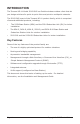
Introduction The Tsunami MP.11 Model 5012-SUR is a flexible wireless outdoor client that let you design solutions for point-to-point links and point-to-multipoint networks. The 5012-SUR is part of the Tsunami MP.
Package Contents Each Tsunami 5012-SUR shipment includes the items listed in the following table. Verify that you have received all parts of the shipment. Note: Cables are not provided with the unit.
Hardware and Software Installation IMPORTANT! Before installing this product, see “Safety and Regulatory Information” on the product CD for important safety and regulatory compliance information. IMPORTANT! All units must be installed by a suitably trained professional installation technician or by a qualified installation service.
Step 1: Choose a location To make optimal use of the unit, you must find a suitable location for the hardware. The range of the unit largely depends upon the position of the integrated antenna. Proxim recommends you do a site survey, observing the following requirements, before mounting the hardware. ▪ The location must allow easy disconnection of the unit from the power outlet if necessary. ▪ The unit must not be covered and the air must be able to flow freely around the unit.
Step 2: Attach cables Note: Depending on your application and location, you may find it easier to mount the unit before you attach cables to it. If this is the case, remove the cable cover (as explained in step 1 below), and then complete Step 3: Mount Unit to Pole. Return to this step for cabling instructions. 1. With the laying unit face down, depress both buttons on the back of the 5012-SUR unit, and pull the plastic cover downward to open. Remove cover. 2. Connect one end of an Ethernet cable (5.
a switch, hub, or patch panel. ▪ Use a cross-over Ethernet cable or adapter if you are connecting the unit to a single computer or most router ports.
Step 3: Mount Unit to Pole Mount the 5012-SUR to a pole as follows: 1. Using a screwdriver, turn the screw on the band clamp counter-clockwise until the clamp opens. 2. Place the back of the 5012-SUR against the pole such that the pole fits into the curved portion of the unit. 3.
5. Repeat procedure to attach other band clamp through bottom opening in the 5012-SUR unit. Note: Do not fully tighten band clamps; you must first ensure a functional link to the BSU (Step 4: View LEDs/Adjust Mounting). The mounted unit, using the optional Proxim universal pole mounting kit (P/N 1087-UMK), is shown below.
Step 4: View LEDs/Adjust Mounting LEDs are located in the cable compartment. When the unit is powered on, the 5012-SUR performs startup diagnostics. When startup is completed, the LEDs show the operational state of the 5012SUR. The following table shows the status of the LEDs when the 5012-SUR is operational.
Status Power Wireless Link Ethernet Link WORP linked, no traffic on interface US: Solid green or yellow Blinking green or yellow Off: No Ethernet WORP linked, normal operation; passing traffic EU/WD: Solid green or yellow US: Solid green or yellow Solid amber: 10 Mbps Solid green or yellow: 100 Mbps Blinking green or yellow EU/WD: Solid green or yellow Off: No Ethernet Solid amber: 10 Mbps Solid green or yellow: 100 Mbps System failure Solid Red N/A N/A Bootloader mode Permanent Solid Am
Step 5: Close Cable Compartment 1. Ensure that the Ethernet cable is properly routed and exiting the unit through the notch at the bottom of the cable compartment. 2. Position the cable cover so that the notch in the cover fits over the Ethernet cable (not pictured) and the large tabs on the cover are aligned below the holes in the unit. 3. Align the small tabs in the bottom cover with the holes in the unit. 4.
The assembly with the cable cover attached is shown below.
Step 6: Tighten Band Clamps 1. Using a 5/16” nutdriver or a screwdriver, fully tighten both band clamps (maximum torque 50 kg-cm/3.6 lbf-ft). 2. Secure Ethernet cable to the pole with cable ties. Provide some slack between the unit and the first cable tie, which should be within 12 inches of the unit. Continue to secure cable with cable ties at 3-foot intervals. The final assembly, using the optional Proxim universal pole mounting kit (P/N 1087-UMK), is shown below.
Step 7: Install Documentation and Software To install the documentation and software on a computer or network: 1. Place the CD in a CD-ROM drive. The installer normally starts automatically. (If the installation program does not start automatically, double click setup.exe on the installation CD.) 2. ▪ ▪ The following documentation and software products are installed: Available from Start > All Programs > Tsunami > MP.
Initialization Connecting to the unit requires either: ▪ A direct physical connection with an Ethernet cable or with a serial RS-232 cable ▪ A network connection Connecting with the Ethernet cable allows you to use of the Web Interface and SNMP in addition to the CLI. Connecting with a serial connection allows you to configure and manage the unit with the CLI. Using a serial connection, you can access the unit through a terminal emulation program such as HyperTerminal.
2. Select the unit for which you want to set the IP address and click Change. The Change dialog window is displayed. 3. To set the IP address manually, ensure that Static is selected as the IP Address Type and fill in the IP Address and Subnet Mask suitable for the LAN subnet to which the unit is connected. To set the IP address dynamically, ensure that Dynamic is selected as the IP Address Type. The unit will request its IP address from a DHCP server on your network. 4.
Accessing the Web Browser To access the unit with a Web browser: 1. Start your Web browser and enter the IP address of the unit in the Address box. The Web address should appear as http:// (for example, http://10.0.0.1). A login window is displayed. 2. A login window is displayed. Do not fill in the User name; enter only the default password public or the configured password. 3. Upon successful login, the System Status window is displayed.
Accessing the Command Line Interface Ethernet Port To use the CLI through the Ethernet port, you must have a telnet program, the CLI password, and the unit’s IP address. To access the unit through Ethernet on a Windows PC: 1. Open a DOS command window: from the Windows Start menu, select Run; enter cmd. 2. In the DOS window displayed, enter the IP address (for example, telnet 10.0.0.1). 3. Click OK to start the telnet program; you are prompted for your password. 4.
Default Settings Setting Default Mode of Operation Bridge Routing Disabled IP Address Assignment Static IP Address 10.0.0.1 Subnet Mask 255.255.255.0 Default Router IP Address 10.0.0.1 Default TTL 64 RIPv2 (if in routing Mode) Enabled Base Station System Name Network Name OR_WORP Frequency Channel Channel 149, 5.
Setting Default Multi-Frame Bursting Enabled Storm Threshold Broadcast/Multicast Unlimited Broadcast Protocol Filtering All Protocols Allowed Dynamic Data Rate Selection Disabled Roaming Disabled NAT Disabled Intra-Cell Blocking Disabled Country Selection US-only device–US World device – GB DHCP Server Disabled DHCP Relay Disabled Spanning Tree Protocol Disabled Antenna Gain (For DFS Threshold compensation) 0 Satellite Density Large VLAN Mode BSU: Transparent mode SU: Transparen
Technical services and support If you are having trouble utilizing your Proxim product, please review the Installation and Management Guide and the additional documentation provided with your product. If you require additional support, please refer to the “Technical Services and Support” chapter in the Installation and Management Guide for details about the information you will need to gather before using the Support Options listed below.