
User's Manual
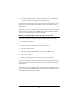


Table Of Contents
- Contents
- Introduction
- Wireless Networking With the Base Station
- Installing the Base Station
- Software Installation for Adapters
- Symphony Composer Installation Wizard
- Symphony Maestro Configuration Tool
- Symphony Location Switcher
- Using the Wireless Network
- About the Base Station
- Uninstalling Symphony Products
- Troubleshooting
- How to Reach Technical Support
- Specifications
- Regulatory Information
- Index
44
❑ Link LED: Located to the left of the Ethernet ports. This LED lights
up when a physical connection exists between the Base Station and
an attached Ethernet device. The LED will not light up if a damaged
or improper Ethernet cable is attached.
Ports and Buttons
The ports and buttons on the Base Station’s back panel (shown in Figure 5) are
described below:
❑ Ethernet Port I: This 10/100 Mbps port is wired like a standard NIC
(network interface card). Use a standard (straight through) Ethernet
cable to connect Port I to an Ethernet hub or to device wired like an
Ethernet hub, such as a cable modem or DSL modem.
❑ Ethernet Port II: This 10/100 Mbps port is wired like an Ethernet
hub. Use a standard (straight through) Ethernet cable to connect Port
II to a stand-alone PC or to a device wired like an Ethernet NIC.
Note:
Use either Port I or Port II. You cannot use the two Ethernet
ports simultaneously.
❑ Teach button: When this button is pressed, the Base Station will
send out a notification that allows other Symphony products that are
operating in learn mode to join the wireless network.
❑ Learn button: When this button is pressed, the Base Station will
enter learn mode to listen for network information from another
Symphony product that is operating in teach mode.
Note:
Do not press either the Teach or Learn button unless directed to
do so by the Symphony Composer Installation Wizard or by a
Symphony Technical Support representative.