Harmony Harmony 802.
Copyright © 2002 Proxim Corporation, Sunnyvale, CA. Covered by one or more of the following U.S. patents: 5,231,634; 5,875,179; 6,006,090. This user’s guide and the software described in it are copyrighted with all rights reserved. No part of this publication may be reproduced, transmitted, transcribed, stored in a retrieval system, or translated into any language in any form by any means without the written permission of Proxim Corporation.
Declaration of Conformity Déclaration de Conformité Konformitätserklärung The Manufacturer: Proxim Europe B.V. Le Constructeur: Der Hersteller: Address: Addresse: Addresse: Prins Bernhardplein 200 1097 JB, P.O. Box 94071, 1090 GB Amsterdam, The Netherlands Declares that the Product: Déclare que le Produit: Erklärt, dass das Produkt: Type: Model: Harmony 802.
For Indoor Use Only These products are for indoor use only. Uniquement pour usage d'intérieur. Somente para uso interno. Solamente para el uso interior. Per uso al coperto solamente. Für Innen Verwendung nur. Nemlig indendørs hjælp bare. For indoor bruk bare. För indoor användning enda. Voor overdekt toepassing uitsluitend. Indoor käyttöä varten vain. Για την εσωτερική χρήση µόνο. Product Approvals Proxim will only ship products that are type approved in the destination country.
Table of Contents Chapter 1 - Introduction .................................................................................. 6 The Harmony Family ....................................................................................... 7 System Requirements ....................................................................................8 The Product Package .....................................................................................8 Harmony 802.11a Access Point Models .......................
Chapter 1 Introduction Thank you for choosing Proxim’s Harmony 802.11a Access Point, a member of Proxim’s Harmony wireless infrastructure family. The Harmony 802.11a Access Point complies with the IEEE 802.11a wireless standard to provide mobile clients with network connectivity at high speed data rates of up to 54 Mbps (up to 108 Mbps in 2XTM mode*). The Harmony 802.11a Access Point is used on its own or in conjunction with a Harmony Access Point Controller. An independent, stand-alone Harmony 802.
Introduction 7 The Harmony Family The Harmony 802.11a Access Point is a member of a product family that provides a complete wireless networking solution. • The Harmony Access Point Controller Model 7560 centralizes the management, security, and filtering capabilities of a wireless LAN. The Access Point (AP) Controller communicates with Harmony Access Points over the Ethernet network to provide wireless network access for mobile clients.
Introduction 8 System Requirements To begin using the Harmony 802.11a Access Point, you must have the following items installed on your local network: • A 10Base-T Ethernet or 100Base-TX Fast Ethernet switch or hub • At least one 802.11a adapter Note: If you want to create a Harmony System that provides centralized management, configuration, filtering, and security, you will also need at least one Harmony Access Point Controller (with firmware version 2.0 installed, although version 2.
Introduction 9 Harmony 802.11a Access Point Models There are three models of the Harmony 802.11a Access Point available. All three units are identical except for the differences noted below. Model 8569/8570 • These two models are identical (they have different part numbers for marketing purposes) • Includes two integral antennas that provide antenna diversity; these antennas cannot be removed from the unit • Provides up to eight independent Channels in 802.
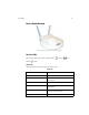
Introduction 10 Access Point Overview Figure 1: Harmony 802.11a Access Point Model 8569/8570 Top Panel LEDs The top panel LEDs are (from left to right) the Status Ethernet Wireless and LEDs. Status LED The Status LED gives information about the Access Point.
Introduction 11 Wireless LED The Wireless LED blinks green when the Access Point receives data packets over the wireless network. Ethernet LED The Ethernet LED blinks green when the Access Point receives data packets over the Ethernet port. Rear Panel Figure 2: Harmony 802.11a Access Point Model 8569/8570 Rear Panel Ethernet Port This port connects the Access Point to your 10/100Base-T Ethernet network using a straight-through Ethernet cable.
Introduction 12 Power Port The Harmony 802.11a Access Point has a power port on its back panel. The voltage range for the Access Point’s power connector is 10-26 VDC. Proxim recommends that you connect only the Class 2 power supply (12V, 1 Amp) provided with the product to the power port. In addition, the Access Point can accept power from a Harmony Power System, which is an alternative power source to the supplied Class 2 power supply. The Harmony Power System is sold separately.
Introduction 13 The IEEE 802.11a Specification In 1997, the Institute of Electrical and Electronics Engineers (IEEE) adopted the 802.11 standard for wireless devices operating in the 2.4 GHz frequency band. This standard includes provisions for three radio technologies: direct sequence spread spectrum, frequency hopping spread spectrum, and infrared. Devices that comply with the 802.11 standard operate at a data rate of either 1 or 2 Mbps. In 1999, the IEEE modified the 802.
Introduction 14 Wireless Network Topologies The Harmony 802.11a Access Point is used to extend the capability of an existing Ethernet network to devices on the 802.11a wireless network. The 802.11a devices can connect to a single Access Point, or several Access Points can be configured to form a single wireless network over a large area, allowing mobile clients to roam from one Access Point to another. Connecting to a Single AP Mobile clients equipped with 802.
Introduction 15 Roaming Between Multiple Access Points For larger environments, Harmon 802.11a client devices may roam from one 802.11a Access Point to another while maintaining the same network connection. The 802.11a Access Points establish coverage areas or cells similar in concept to those of a cellular phone network. The mobile clients will connect to any 802.11a Access Point that is within range. Figure 4: Roaming Between APs Each 802.
Introduction 16 Guidelines for Roaming • An 802.11a client can only roam between 802.11a Access Points. An 802.11a client cannot communicate with 802.11b Access Points. • All 802.11a Access Points must have the same SSID. • All workstations with 802.11a client adapters installed must use either an SSID of “any” or the same SSID as the Access Points that they will roam between. • All 802.11a Access Points and clients must have the same security settings to communicate.
Introduction 17 When to Use an AP Controller Stand-alone Harmony 802.11a Access Points are well suited for small office environments. However, as you increase the number of Access Points or the complexity of your network, it can become more difficult to efficiently manage the wireless infrastructure. In these cases, you can add an Access Point Controller to provide centralized management and configuration for the Access Points.
Chapter 2 Installation This chapter describes how to install the Harmony 802.11a Access Point. If you intend to use the Harmony 802.11a Access Point with a Harmony Access Point (AP) Controller, install the AP Controller first. Note: The AP Controller must have firmware version 2.0 installed to support the Harmony 802.11a Access Point (version 2.1 or greater is recommended). Confirm that the AP Controller has the latest firmware version before installing the 802.11a Access Point.
Installation 19 Radio Frequency Interference Requirements The Harmony 802.11a Access Point Models 8569 and 8570 operate in the frequency range of 5.15 to 5.35 GHz; they are restricted to indoor use due to their operation in the 5.15 to 5.25 GHz frequency range. FCC 15.407(e) requires that these devices be used indoors in the frequency range of 5.15 to 5.25 GHz to reduce the potential for harmful interference to co-channel Mobile Satellite systems.
Installation 20 Installation Determine the best location for the Harmony 802.11a Access Point using the following considerations: • The length of the Ethernet cable that connects the Access Point to the network must not exceed 100 meters. • Place the Access Point indoors, on a flat, sturdy surface as far from the ground as possible, such as on top of a desk or bookcase, keeping clear of metal obstructions and away from direct sunlight.
Installation 21 4. The Link LED on the rear panel will light to indicate that the Access Point has a network connection. The LED is lit green if connected to a 100Base-TX network and lit amber if connected to a 10Base-T network. 5. By default, the Harmony 802.11a Access Point will attempt to find an AP Controller to partner with.
Installation 22 Mounting Instructions The Harmony 802.11a Access Point ships with a wall mounting kit so that the unit can be mounted to a wall or ceiling. The wall mounting kit contains the following parts: • One AP Mounting Disk • Two Plastic Wall Mount Anchors • Two #6x0.
Installation 23 2. Attach the Access Point to the mounting disk by aligning the Access Point’s mounting holes (located on the underside of the unit) over the mounting disk’s raised notches (shown below). Mounting Notches Figure 5: AP Mounting Disk Notches 3. Slide the Access Point over the mounting disk until it locks into place. 4. Ceiling mounting is now complete. Return the instructions on page 20 to install the Access Point cabling.
Installation 24 4. Align one of the #6 wood screws with one of the mounting holes (see Figure 6) and screw it into one of the wall anchors or directly into the wall. Do not tighten. 5. Insert the second screw into the remaining mounting hole and screw it into the remaining wall anchor or directly into the wall. 6. Tighten the two screws to secure the mounting disk to the wall. 7.
Chapter 3 Configuration This chapter describes how to configure and manage a stand-alone Harmony 802.11a Access Point in Independent mode using its Web configuration tool. Note: If you have one or more Harmony AP Controllers on the network, refer to the Harmony Access Point Controller User’s Guide for information on how to configure and manage Access Points using an AP Controller.
Configuration 26 Note: 4. To check a computer’s IP address assignment, open a Command Prompt window and type ipconfig. If you are using a computer equipped with an 802.11a wireless adapter, be sure it is configured to connect to an Access Point as follows: • SSID: any • Mode: Infrastructure • Security Level: No Security 5. Open a Web browser such as Microsoft Internet Explorer 5 on the computer. 6. In the Address box, enter the IP Address of the Access Point (such as 192.168.0.2) and press Enter.
Configuration 27 9. When prompted, enter default in the Password field and click OK. Note: The User Name field is not used; you can enter any value in this field or leave it blank. The default Password is default; it is case sensitive. You can change the Password at any time from the System Access configuration screen (see “System Access” on page 38). 10. Configure the Access Point’s settings as necessary or view the available statistics.
Configuration 28 Status Tab The Status tab displays the Access Point Status screen, which gives information about the Access Point. Software Version This field reports the Flash Code version installed on the Access Point. Periodically, Proxim makes new Access Point Flash Code available on its Web site with upgrade instructions. If you are experiencing a problem with your equipment, a Proxim Technical Support representative may ask you to report the device’s Flash Code version.
Configuration 29 Configure Tab The Configure tab displays the Configuration screens, which offer options for the Access Point’s Network, Radio, and System Access parameters. Network This screen is where you can set the Access Point’s IP (Internet Protocol) and SNMP (Simple Network Management Protocol) parameters. If you make any changes to these settings, you must reboot the Access Point in order for them to take effect.
Configuration 30 SNMP The Harmony 802.11a Access Point supports SNMP version 2c (SNMPv2c) and a subset of the following Management Information Base (MIB) files: • System Group, Interface Group, and IP Group of MIB-II (RFC 1213) • Ethernet-like MIB (RFC 1643) • IEEE 802.11 MIB These MIBs describe the 802.11a AP parameters and statistics that can be viewed and/or configured over SNMP.
Configuration 31 • Restrict Read-Only Community to IP: Enter an IP address in this field to specify the only SNMP Manager permitted access to the AP’s Read-Only Community. A value of 0.0.0.0 means that there is no restriction; any IP address can access the community. • Read-Write Community: This parameter specifies a community supported by the Access Point. Actions permitted by this community are read-write (GET, GET-NEXT, and SET). By default, the community is set to “private.
Configuration 32 Enable 2X Mode The Harmony 802.11a Access Point supports 2XTM mode, a high-speed operating mode that can provide data rates of up to 108 Mbps, twice the speed of standard 802.11a devices. By default, 2X mode is disabled. Note: Products sold in Europe, Japan, and Singapore do not support 2X mode. When 2X mode is disabled, the Access Point complies with the IEEE 802.11a standard and can achieve speeds of up to 54 Mbps.
Configuration 33 Note: See “Radio Frequency Interference Requirements” on page 19 for important regulatory information concerning Channel selection. A 2X Channel requires twice the bandwidth of a standard 802.11a Channel. For Europe: The Model 8570 Access Point can use one of eight Channels: Channel 36 (5.18 GHz), Channel 40 (5.20 GHz), Channel 44 (5.22 GHz), Channel 48 (5.24 GHz), Channel 52 (5.26 GHz), Channel 56 (5.28 GHz), Channel 60 (5.30 GHz), or Channel 64 (5.32 GHz).
Configuration 34 Security The Harmony 802.11a Access Point offers three security settings when operating in Independent mode: No Security (None), WEP, and 802.1x. Note: The Harmony Security Protocol is only available when an 802.11a Access Point is partnered with an AP Controller. WEP The IEEE 802.
Configuration 35 Proxim supports the following RADIUS servers for use with a Harmony 802.11a Access Point: • Microsoft Windows 2000 Internet Authentication Service (IAS) Server • Funk Odyssey Server Note: You may also need to install additional components based upon the server’s requirements and EAP authentication type. For example, EAP-TLS requires a Certificate Authority (CA) and that digital certificates be installed on the RADIUS server and each wireless device.
Configuration 36 6. Enter one to four global WEP Keys in the fields provided. • For 64-bit encryption, a WEP Key is 10 hexadecimal digits (0-9 and A-F). • For 128-bit encryption, a WEP Key is 26 hexadecimal digits (0-9 and A-F). • For 152-bit encryption, a WEP Key is 32 hexadecimal digits (0-9 and A-F). 7. Select one of the configured keys as the Default Key; this key is used to encrypt outgoing broadcast packets. 8. Click Apply to Radio to save the changes. 9.
Configuration 37 RTS/CTS The 802.11a standard supports optional RTS/CTS communication. Without RTS/CTS, a sending radio listens to see if another radio is already using the medium before transmitting a data packet. If the medium is free, the sending radio transmits its packet. However, there is no guarantee that another radio is not transmitting a packet at the same time, causing a collision.
Configuration 38 System Access The System Access parameter changes the web configuration tool’s Password. A user is prompted to enter a User Name and Password when attempting to access the Access Point’s web configuration tool. There is no configuration option for the User Name; it can be any value (even blank). The Password cannot exceed 12 characters and is case sensitive. The password default is the word “default”.
Configuration 39 Statistics Tab The Statistics tab allows access to the Radio and Ethernet Statistics screens. Radio Statistics The Radio Statistics provide information concerning the number of packets sent and received by an Access Point over the radio network. The following Radio Statistics are available for an 802.11a Access Point: Transmit Statistics • Unicast Packets: Number of unicast packets transmitted. Unicast packets are destined for a single network node.
Configuration 40 • Multiple Retries: This statistic reports the number of packets that required more than one retry before the AP received an acknowledgment. • Retries Exceeded: This statistic reports the number of packets for which the AP did not receive an acknowledgment within the maximum number of retries. • Transmissions Discarded: This statistic reports the number of packets discarded by the radio due to a transmission error, such as exceeding the number of retries.
Configuration 41 • Packets Filtered: This statistic displays the number of packets that the Access Point did not forward to the radio network because the packet’s destination was listed in the Access Point’s forwarding table as a node on the Ethernet network. • Buffer Fails: An Access Point temporarily stores the packets it receives from one network interface before forwarding them to the other.
Chapter 4 Troubleshooting The Harmony 802.11a Access Point is designed to be very easy to install and operate. However, if you experience difficulties, use the information in this chapter to help diagnose and solve problems. Also, if you have an AP Controller, refer to the Harmony Access Point Controller User’s Guide for additional troubleshooting suggestions. If you cannot resolve a problem, contact Proxim Technical Support. See “Technical Support and Training” on page 53.
Troubleshooting 43 Range Every environment is unique with different obstacles, barriers, materials, etc., and, therefore, it is difficult to determine the exact range that will be achieved without testing. Radio signals may reflect off of some obstacles or be absorbed by others depending on their construction. The IEEE 802.11a specification supports eight data rates: 54 Mbps, 48 Mbps, 36 Mbps, 24 Mbps, 18 Mbps, 12 Mbps, 9 Mbps, and 6 Mbps.
Troubleshooting 44 • If possible, avoid mounting the Access Point to walls made of reinforced concrete or masonry. • For Model 8571, you must use two antennas. However, it is not necessary to use two antennas of the same type. (Your decision as to which antennas to use will vary depending on the specifics of your AP installation and the site’s coverage requirements.
Troubleshooting 45 Common Problems and Solutions Symptom/Question Possible Solution/Answer I forgot my password and now I can’t access the Access Point’s configuration tool. Contact Proxim Technical Support for assistance. I can’t remember the static IP address that I assigned to the Access Point. Contact Proxim Technical Support for assistance. I’m using the Access Point in Independent mode.
Troubleshooting 46 Symptom/Question Possible Solution/Answer I have a Harmony AP Controller but the 802.11a Access Point does not automatically register with it. The AP keeps booting up in Independent mode. • Confirm that the Link LED is on for both the AP and the AP Controller. If the LED is not on, check your connection to the local Ethernet network. Also, try another Ethernet cable. • Try repowering the unit. The Access Point will try to contact an AP Controller during boot-up.
Troubleshooting 47 Symptom/Question Possible Solution/Answer My office has an existing 802.11b network. Is the Harmony 802.11a Access Point compatible? No. 802.11a devices are not compatible with 802.11b devices. I want to install a Harmony 802.11a network in my office that has an existing 802.11b network. Will the 802.11a network interfere with the 802.11b network? No. 802.11a and 802.11b devices will not interfere with each other since they operate at different frequencies. 802.
Appendix A Technical Specifications The following technical specification is for reference purposes only. Actual product’s performance and compliance with local telecommunications regulations may vary from country to country. Proxim Corporation will only ship products that are type approved in the destination country. Specifications General Ethernet Architecture .......................Transparent bridge Safety ..............................................UL; CSA; CE Compatibility ....................
Management Automatic Configuration ..................SmartAttach™ via AP Controller, includes security levels, filtering, radio parameters, IP address and channels Remote Access .................................HTTP Firmware Upgrade ............................Via Upgrade tool or AP Controller SNMP Compliance ............................Available; see “SNMP” on page 30 Statistics..........................................Ethernet and radio Radio Radio Data Rate ...............................
Environmental Operating Temperature ....................0ºC to +50ºC Storage Temperature ........................-25ºC to 70ºC Humidity ..........................................10-90% (non-condensing) Physical Weight .............................................8.2 ounces (232 g) Size..................................................6.0" L x 6.5" W x 1.5" H (152 mm x 165 mm x 38 mm) Mounting .........................................Desk surface or wall/ceiling mount UL Listed Power Supply ............
Parameters Note: These are the parameters that are available when the Harmony 802.11a Access Point is operating in Independent mode. Parameter Range Default Use DHCP Yes, No Yes System Access Password Up to 12 characters default IP Address - Assigned by DHCP server Subnet Mask - Assigned by DHCP server Default Gateway - Assigned by DHCP server Use SNMP Yes, No No Read-Only Community - public Restrict Read-Only Community to IP - 0.0.0.
Parameter Range Default SSID Up to 32 characters default Send Rate Automatic selection by Access Point, or select transmit rate from among 54, 48, 36, 24, 18, 12, 9, and 6 Mbps in 802.11a mode and from among 108, 96, 72, 48, 36, 24, 18, and 12 Mbps in 2X mode Automatic Security None, WEP, 802.1x None Radius Server - 0.0.0.
Appendix B Technical Support and Training If you are having a problem using a Harmony 802.
Index A Access Point Controller. See Harmony Access Point Controller Access Point Overview ................................................................ 10–12 Antenna ........................................................................................ 9 Antenna Placement ................................................................... 43–44 Authorization Table ......................................................................... 17 B Buffer Fails .........................................
Ethernet Statistics .................................................................... 40–41 Ethernet-like MIB ........................................................................... 30 Extensible Authentication Protocol (EAP) ........................................ 34–36 F FCC .................................................................................... 2, 18, 20 FCS Errors .................................................................................... 40 Fragmentation ............
L LED Error Codes ............................................................................ 42 LEDs ...................................................................................... 10–11 Link Down Trap ............................................................................. 30 Link LED .................................................................................. 11, 46 Link Up Trap ................................................................................. 30 M MAC Address ..
R Radio Configuration Parameters .................................................... 31–37 Radio Statistics ........................................................................ 39–40 RADIUS Server ......................................................................... 34–35 Radius Server IP Address .................................................................. 35 Radius Server Shared Secret.............................................................. 35 Range ...............................
Transmissions Discarded ................................................................. 40 Transmit Rate. See Send Rate Transmit Statistics .................................................................... 39–40 Trap Community ............................................................................. 31 Traps.......................................................................................... 30 Troubleshooting Suggestions ......................................................