
Access Point User Guide
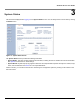
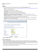
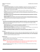
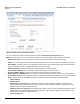
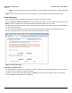
Table Of Contents
- Introduction
- Installation and Initialization
- System Status
- Advanced Configuration
- System
- Network
- Interfaces
- Management
- Filtering
- Alarms
- Bridge
- QoS
- Radius Profiles
- SSID/VLAN/Security
- Monitoring
- Commands
- Troubleshooting
- Command Line Interface (CLI)
- General Notes
- Command Line Interface (CLI) Variations
- CLI Command Types
- Using Tables and Strings
- Configuring the AP using CLI commands
- Set Basic Configuration Parameters using CLI Commands
- Set System Name, Location and Contact Information
- Set Static IP Address for the AP
- Change Passwords
- Set Network Names for the Wireless Interface
- Enable 802.11d Support and Set the Country Code
- Enable and Configure TX Power Control for the Wireless Interface(s)
- Configure SSIDs (Network Names), VLANs, and Profiles
- Download an AP Configuration File from your TFTP Server
- Backup your AP Configuration File
- Set up Auto Configuration
- Other Network Settings
- Configure the AP as a DHCP Server
- Configure the DNS Client
- Configure DHCP Relay
- Configure DHCP Relay Servers
- Maintain Client Connections using Link Integrity
- Change your Wireless Interface Settings
- Set Ethernet Speed and Transmission Mode
- Set Interface Management Services
- Configure Syslog
- Configure Intra BSS
- Configure Wireless Distribution System
- Configure MAC Access Control
- Set RADIUS Parameters
- Set Rogue Scan Parameters
- Set Hardware Configuration Reset Parameters
- Set VLAN/SSID Parameters
- Set Security Profile Parameters
- CLI Monitoring Parameters
- Parameter Tables
- CLI Batch File
- ASCII Character Chart
- Specifications
- Technical Support
- Statement of Warranty
- Regulatory Compliance
Advanced Configuration AP-4000 Series User Guide
Network
50
Figure 4-6 DHCP Server IP Address Table - Edit Entries
To add an entry, enter the IP Address of the DHCP Server and a comment (optional), and click OK.
To edit an entry, make changes to the appropriate entry. Enable or disable the entry by choosing Enable or Disable from
the Status drop-down menu, and click OK.
Link Integrity
The Link Integrity feature checks the link between the AP and the nodes on the Ethernet backbone. These nodes are
listed by IP address in the Link Integrity IP Address Table. The AP periodically pings the nodes listed within the table. If
the AP loses network connectivity (that is, the ping attempts fail), the AP disables its wireless interface(s). Note that this
feature does not affect WDS links (if WDS links are configured and enabled).
NOTE: Link integrity cannot be configured when the AP is configured to function as a Mesh AP.
You can configure and view the following parameters within the Link Integrity Configuration screen:
• Enable Link Integrity: Place a check mark in the box provided to enable Link Integrity.
• Poll Interval (milliseconds): The interval between link integrity checks. Range is 500-15000 ms in increments of
500 ms; default is 500 ms.
• Poll Retransmissions: The number of times a poll should be retransmitted before the link is considered down.
Range is 0 to 255; default is 5.
• Target IP Address Entry: This entry specifies the IP address of a host on the network that the AP will periodically poll
to confirm connectivity. The table can hold up to five entries. By default, all five entries are set to 0.0.0.0. Click Edit to
update one or more entries. Each entry contains the following field:
– Target IP Address
– Comment (optional)
– Status: Set this field to Enable to specify that the Access Point should poll this device. You can also disable an
entry by changing this field’s value to Disable.