
Access Point User Guide
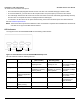
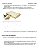
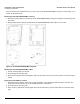
Table Of Contents
- Introduction
- Installation and Initialization
- System Status
- Advanced Configuration
- System
- Network
- Interfaces
- Management
- Filtering
- Alarms
- Bridge
- QoS
- Radius Profiles
- SSID/VLAN/Security
- Monitoring
- Commands
- Troubleshooting
- Command Line Interface (CLI)
- General Notes
- Command Line Interface (CLI) Variations
- CLI Command Types
- Using Tables and Strings
- Configuring the AP using CLI commands
- Set Basic Configuration Parameters using CLI Commands
- Set System Name, Location and Contact Information
- Set Static IP Address for the AP
- Change Passwords
- Set Network Names for the Wireless Interface
- Enable 802.11d Support and Set the Country Code
- Enable and Configure TX Power Control for the Wireless Interface(s)
- Configure SSIDs (Network Names), VLANs, and Profiles
- Download an AP Configuration File from your TFTP Server
- Backup your AP Configuration File
- Set up Auto Configuration
- Other Network Settings
- Configure the AP as a DHCP Server
- Configure the DNS Client
- Configure DHCP Relay
- Configure DHCP Relay Servers
- Maintain Client Connections using Link Integrity
- Change your Wireless Interface Settings
- Set Ethernet Speed and Transmission Mode
- Set Interface Management Services
- Configure Syslog
- Configure Intra BSS
- Configure Wireless Distribution System
- Configure MAC Access Control
- Set RADIUS Parameters
- Set Rogue Scan Parameters
- Set Hardware Configuration Reset Parameters
- Set VLAN/SSID Parameters
- Set Security Profile Parameters
- CLI Monitoring Parameters
- Parameter Tables
- CLI Batch File
- ASCII Character Chart
- Specifications
- Technical Support
- Statement of Warranty
- Regulatory Compliance
Installation and Initialization AP-4000 Series User Guide
AP-4000 Series Hardware Description
21
• The Active Ethernet (AE) integrated module receives ~48 VDC over a standard Category 5 Ethernet cable.
• To use Active Ethernet, you must have an AE hub (also known as a power injector) connected to the network.
• The cable length between the AE hub and the Access Point should not exceed 100 meters (approximately 325 feet).
The AE hub is not a repeater and does not amplify the Ethernet data signal.
• If connected to an AE hub and an AC power simultaneously, the Access Point draws power from Active Ethernet.
Also see Hardware Specifications.
NOTE: The AP’s 802.3af-compliant Active Ethernet module is backwards compatible with all ORiNOCO Active Ethernet
hubs that do not support the IEEE 802.3af standard.
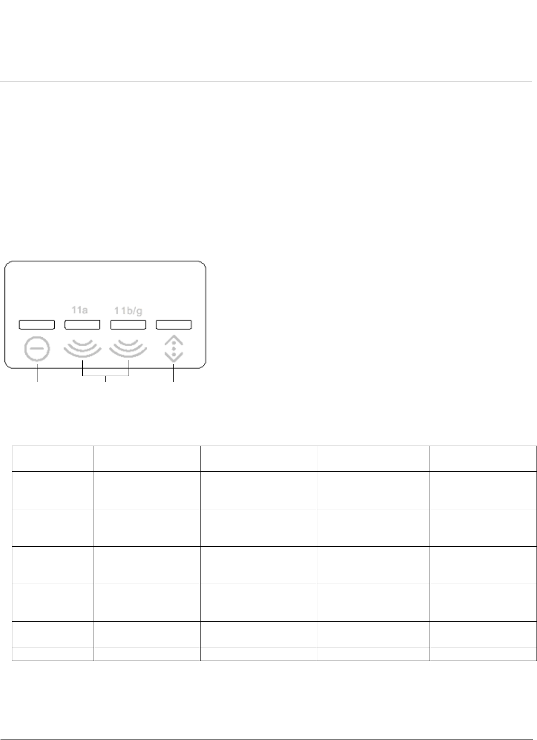
LED Indicators
The top panel of the AP-4000/4000M/4900M has the following LED indicators.
Figure 2-3 LED Indicators on the AP-4000/4000M/4900M Top Panel
The LED indicators exhibit the following behavior:
Indication Power Wireless Interface A
(802.11a radio)
Wireless Interface B
(802.11b/g radio)
Ethernet
Solid Green AP image running. Wireless interface A is
preparing for use.
Wireless interface B is
preparing for use.
Ethernet interface is
connected at 100 Mbps
with no traffic.
Blinking Green n/a Wireless interface A is
transmitting or receiving
wireless packets.
Wireless interface B is
transmitting or receiving
wireless packets.
Ethernet interface is
connected at 100 Mbps
with traffic.
Solid Amber The Bootloader is
loading the application
software.
n/a n/a Ethernet interface is
connected at 10 Mbps
with no traffic.
Blinking Amber The AP is reloading. n/a n/a The Ethernet interface
is connected at 10
Mbps with traffic.
Solid Red Power On Self Test
(POST) running.
n/a n/a n/a
Blinking Red Rebooting. n/a n/a n/a
Power Wireless
Interfaces
Ethernet