
Specifications

System Overview Tsunami MP.11 5012-SUR Installation and Management
Virtual Local Area Networks (VLANs)
33
Virtual Local Area Networks (VLANs)
NOTE: VLANs are configured on the Base Station Unit. See the Tsunami MP.11 5054-R and 2454-R Installation and
Management Guide for more information.
Virtual Local Area Networks (VLANs) are logical groupings of network hosts. Defined by software settings, other VLAN
members or resources appear (to connected hosts) to be on the same physical segment, no matter where they are
attached on the logical LAN or WAN segment. They simplify allowing traffic to flow between hosts and their frequently-
used or restricted resources according to the VLAN configuration.
Tsunami MP.11 5012 units are fully VLAN-ready; however, by default, VLAN support is disabled. Before enabling VLAN
support (by assigning a VLAN Management ID), certain network settings should be configured and network resources
such as VLAN-aware switches should be available, dependent upon the type of configuration.
VLANs are used to conveniently, efficiently, and easily manage your network in the following ways:
• Manage VLAN configuration from a single window
• Define groups
• Reduce broadcast and multicast traffic to unnecessary destinations
• Improve network performance and reduce latency
• Increase security
• Secure network restricts members to resources on their own VLAN
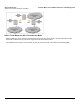
VLAN tagged data is collected and distributed through a unit’s Ethernet interface. The units can communicate across a
VLAN-capable switch that analyzes VLAN-tagged packet headers and directs traffic to the appropriate ports when the
units are working in their Transparent mode.
VLAN features can be managed via:
• The BSU’s Web interface
• The Command Line Interface (see “Command Line Interface” in the Reference Manual)
• SNMP (see the MIBs provided on the product CD)
VLAN Modes
Transparent Mode
Transparent mode applies to both the SU and the BSU. This mode is equivalent to NO VLAN support and is the default
mode. It is used when the devices behind the SU and BSU are both VLAN aware or unaware. The SU/BSU transfers both
tagged and untagged frames received on the Ethernet or WORP interface. Both tagged and untagged management
frames can access the device.
Trunk Mode
Trunk mode VLAN applies to both the SU and the BSU. It is used when all devices behind the SU and BSU are VLAN
aware. The SU and BSU transfer only tagged frames received on the Ethernet or WORP interface. Both tagged and
untagged management frames can access the device.
Access Mode
Access mode applies only to the SU. It is used when the devices behind the SU are VLAN unaware. Frames to and from
the Ethernet interface behind the SU map into only one VLAN segment. Frames received on the Ethernet interface are
tagged with the configured Access VLAN ID before forwarding them to the WORP interface. Both tagged and untagged
management frames can access the device from the WORP interface. However, only untagged management frames can
access the device from the Ethernet Interface.