
Specifications

Installation and Initialization Tsunami MP.11 5012-SUR Installation and Management
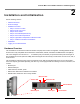
Installation Procedure
20
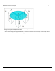
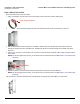
Step 4: View LEDs/Adjust Mounting
LEDs are located in the cable compartment.
When the unit is powered on, the 5012-SUR performs startup diagnostics. When startup is completed, the LEDs show
the operational state of the 5012-SUR.
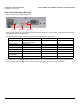
The following table shows the status of the LEDs when the 5012-SUR is operational.
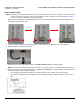
If a wireless link is not established with the BSU, adjust the direction of the unit so that the integrated antenna is more
precisely aimed toward the BSU. When the Power LED is solid green, the link is correctly established.
Status Power Wireless Link Ethernet Link
Starting up Three red blinks followed by a
temporary solid amber
N/A N/A
Radio scanning Blinking green N/A N/A
WORP link is up Solid green N/A N/A
No WORP link Blinking amber/green N/A N/A
System failure Solid red N/A N/A
No traffic on interface N/A Solid green Solid green
Normal operation /
passing traffic
Solid green Blinking green Blinking green
Bootloader mode Permanent solid amber N/A N/A
Power Wireless Ethernet