
Installation guide

Determining Range and Clearance Tsunami MP.11 Antenna Installation Guide
Calculations
33
Procedure
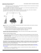
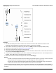
1. Start with the transmit power and the number of the channel to be used in dBm. Subtract the total loss of all
transmission elements between the antenna and the radio on one side of the link (dB).
2. Add the dBi of the antenna you will be using. The total is the EIRP (equivalent isotropically radiated power).
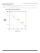
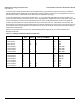
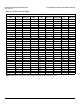
3. Determine your link budget from the Distance and Link Budget table.
4. Add the gain of the antenna on the second side of the link.
5. Subtract the total loss of all transmission elements between the antenna and the radio on the second side of the link.
The result is the Received Signal Level (RSL).
6. From the Receiver Sensitivity tables in your radio’s Installation and Management Manual’s “Technical Specifications”
appendix, find the dBm value for the data rate used for the link.
7. Subtract this value from the Received Signal Level; this is the Fade Margin.
NOTES:
• The RSL must be higher than the Receiver Sensitivity plus the fade margin for a good link. The amount of Fade
Margin indicates the reliability of the link; the more Fade Margin, the more reliable the link.
• The path loss must be smaller than the link budget minus the minimum required fade margin. The maximum
ranges cause the path loss plus the fade margin to be the same as the link budget.
The results of this link budget calculation are very important for determining any potential problems during installation. If
you have calculated the expected RSL, you can verify that it has been achieved during installation and troubleshooting, if
necessary.