
Installation guide

Installing the Link Tsunami MP.11 Antenna Installation Guide
Determining Optimal Antenna Placement
19
Determining Optimal Antenna Placement
To achieve maximum performance of your wireless outdoor link, the outdoor antenna must have clear line-of-sight to the
antenna of the other unit. Although the radio signal can work well without line-of-sight in urban environments in which the
signal is transported by reflection rather than being direct, the best results are achieved in line-of-sight conditions.
Line-of-sight is defined as:
• No obstacles in the direct path between the antennas (antenna beam)
• No obstacles within a defined zone around the antenna beam
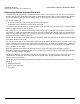
You should be aware that the shape of an antenna beam is not straight and narrow like a laser beam. The antenna beam
contains a bulged area known as Fresnel Zone.
The 1
st
Fresnel zone is an imaginary boundary line offset along the direct signal path. This boundary is defined as the
point where, if a signal were reflected between the two antennas, it would travel a distance exactly one-half wavelength
longer than the direct-path signal. Each succeeding Fresnel zone boundary adds an additional half-wavelength to the
reflected path distance between the antennas.
Signals reflected from any even-numbered Fresnel zone result in signal cancellation; those from odd-numbered Fresnel
zones add to the direct path signal.
The exact shape and width of the Fresnel Zone is determined by the path length and frequency of the radio signal. The
width as distance from the direct antenna beam is approximately 6.8 m in the middle of the wireless link for a distance of
6 Km and a frequency of 3.5 GHz. This width is also the required clearance of the antenna beam from obstacles in its
path, to avoid loss of radio signal.
When any significant part of this zone is obstructed, a portion of the radio energy is lost, resulting in reduced
performance. Reduced performance can also occur when obstacles close to the antenna beam cause signal reflections
or noise that interfere with the radio signal.
For optimal performance, you must ensure that the type and placement of the antennas leave sufficient clearance of the
Fresnel Zone at the maximum width of the bulge, which is typically at the mid-point between the antennas. See
Determining the Outdoor Range.
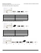
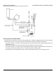
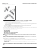
The following figure shows some typical examples of obstacles you must avoid for the directional antenna to operate
effectively:
a. Neighboring buildings
b. Trees or other obstructions
c. Power lines