
Specifications

Installation and Initialization MP.11 5054-R/2454-R Installation and Management
Installation Procedure
23
Step 2: Pre-Assemble the Hardware
1. Unpack the unit and accessories from the shipping box.
2. Note the Ethernet and MAC addresses of the SU, as well as the serial number; these addresses may be used when
configuring the BSU.
NOTE: The serial number is required to obtain support from Proxim. Keep this information in a safe place.
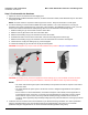
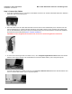
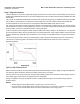
3. You will be attaching an outdoor-rated 24 AWG CAT5 cable (diameter .114 to .250 inches/2.9 to 6.4 mm) (not
provided) to the Power-over-Ethernet port on the back of the unit later in the installation procedure. First, you must
construct the cable and assemble the waterproofing cable covers as described in the following steps:
i. Slide the sealing nut (A) over the bare end of the CAT5 cable.
ii. Slide the lock nut (B) over the bare end of the CAT5 cable.
iii. Slide the RJ45 sealing cap (C) over the bare end of the CAT5 cable.
iv. Terminate the RJ45 connector to the CAT5 cable. Insert into the mating RJ45 connector (D).
v. Slide the RJ45 sealing cap (C) over the RJ45 connector and thread onto enclosure. Hand tighten.
vi. Thread the lock nut (B) onto sealing cap (C), and hand tighten.
vii. Thread the sealing nut (A) onto the lock nut (B), and hand tighten.
CAUTION: Hand-tighten only. Torque values for final installation are provided in Step 8: Complete Installation.
CAUTION: The sealing nut (A) must not be tightened until the sealing cap (C) over the RJ45 connector has been
tightened to the unit during final installation; otherwise, the Ethernet cable may twist and damage.
NOTES:
• The cable must feed through all parts of the weatherproof cap before the RJ45 is crimped on the outdoor
Ethernet a cable.
• The cable between the power injector and the unit must be a straight-through Ethernet cable (without
crossover).
• Due to variance in CAT5 cable diameter, termination techniques of the installer, and the application of
proper tightness of the connectors, it is strongly recommended that the CAT5 cable connector and the
serial connector cap are further secured by external weatherproofing (in addition to the antenna N
connector, where applicable). Butyl weatherproofing tape is the preferred material for securing any external
connector.
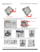
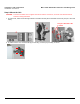
4. Locate the arrow on the back of the unit and determine your desired mounting orientation. For vertical polarization
using the integrated antenna, the arrow should be pointing up (perpendicular to the ground). For horizontal
polarization using the integral antenna, the arrow should be horizontal (parallel to the ground).
B
A
C
D