
Specifications


Installation and Initialization MP.11 5054-R/2454-R Installation and Management
Hardware Overview
17
Hardware Overview
The 5054-R and 2454-R units contain a state-of-the-art wireless radio, an optional high-gain performance flat-panel
antenna, and Power-over-Ethernet (the sole means of power for the unit). For further protection, the unit has internal,
built-in surge protection.
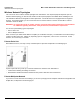
Power and Ethernet Connection
Serial Connection
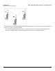
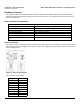
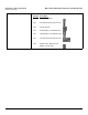
The serial connection is made with an RJ11 to DB9 connector (also referred to as a “dongle”). Connect the RJ11 end to
the unit and connect the serial (DB9) end to your PC to assist you in aligning the antenna and to issue CLI commands.
See the following figure:
\
Figure 2-1 Serial Dongle Diagram
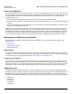
The connections are as follows:
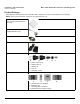
Recommended Cable
Function Power (DC) and Ethernet connection
Type Cat5, UV-shielded and outdoor-rated
Impedance 100 ohms
Recommended cables 4 UTP, 24 AWG, UL rated
Maximum Distance 330 feet / 100 meters
Connector type, unit end RJ45 female, weatherized using weatherproof connector
Connector type, power & Ethernet adapter
end
RJ45
D-Shell RJ11
1NC
22
34
4NC
5 1 + 3 + 5
66
7NC
8NC
9NC