
User's Manual Part 2
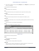
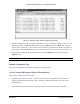

Table Of Contents
- Chapter 4. System Diagnostics and Operating Tips
- Appendix A. Initial Settings
- Appendix B. Installing the Configuration Software and Upgrading Firmware
- Appendix C. Technical Specifications
- Burst-Rate Limit
- Downlink/Uplink Throughput
- Frequency Plans
- Tx Power
- Antenna
- Receiver Sensitivity
- Maximum Distance Between Base Station and Subscriber Unit
- System
- Standards Compliance and Interfaces
- Configuration and Management
- Power/Environment Safety
- Physical Dimension
- Installation Details
- Optional Accessories
- Appendix D. Constructing Power and Ethernet Cables
- Appendix E. Lightning Protection Recommendations
- Appendix F. Technical Support and Training

Tsunami Multipoint Version 1.3 Installation Guide
IB pkts
Shows the number of inbound packets transmitted.
OB pkts
Shows the number of outbound packets received.
OB PE
Shows the number of outbound packet errors.
OB PER
Shows the error rate for outbound packets received.
Time
Shows the cumulative polling time (in seconds).
Figure 26. SU Log 2
Uplink BER Test
The Uplink BER Test determines the BER (bit error rate) of the uplink signal. This is an out-of-service
diagnostic tool and the data connection is terminated for the length of the test. Use this tool to determine
whether the link is stable (that is, there are no bit errors). You can also monitor these test results to fine
tune antenna alignment to get the strongest link possible.
Note: Do not run this test if users are sending data across the radio link.
Follow these steps to run the Uplink BER Test:
1. Open the Base Station Configuration Software.
2. Enter uplber <Terminal ID> to start the test for a particular SU. <Terminal ID> is the Terminal
ID of the SU of interest.
3. Enter berlog 1 to view the test results.
Chapter 4. System Diagnostics and Operating Tips 43
CPN 63179 Issue Date: 01/24/03