
User's Manual Part 2

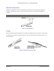
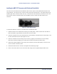
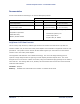
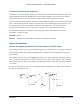
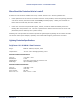
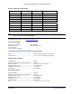
Table Of Contents
- Chapter 4. System Diagnostics and Operating Tips
- Appendix A. Initial Settings
- Appendix B. Installing the Configuration Software and Upgrading Firmware
- Appendix C. Technical Specifications
- Burst-Rate Limit
- Downlink/Uplink Throughput
- Frequency Plans
- Tx Power
- Antenna
- Receiver Sensitivity
- Maximum Distance Between Base Station and Subscriber Unit
- System
- Standards Compliance and Interfaces
- Configuration and Management
- Power/Environment Safety
- Physical Dimension
- Installation Details
- Optional Accessories
- Appendix D. Constructing Power and Ethernet Cables
- Appendix E. Lightning Protection Recommendations
- Appendix F. Technical Support and Training

Tsunami Multipoint Version 1.3 Installation Guide
Pinout and Wiring Specifications:
Surge Side Equipment Side Application Wire Color
Vdc in VDC out 48Vdc White/Orange
RTN in RTN out Ground Orange
Vdc in VDC out 48Vdc White/Brown
RTN in RTN out Ground Brown
Tx+ in Tx+ out Tx + Green
Tx- in Tx- out Tx - White/Green
Rx+ in Rx+ out Rx + Violet
Rx- in Rx- out Rx - White/Violet
GND GND Shield, if req. N/A
Note: VDC in (out) and RTN in (out) pinouts are based upon applying a negative or positive 48 FDC to the VDC
terminal and applying the dc ground to RTN.
For additional information, go to www.polyphaser.com.
Contact Information:
Polyphaser Corporation (702) 782-2511
2225 Park Place (702) 782-4476 (fax)
P. O. Box 9000
Minden, Nevada 89424
Transtector Systems ALPU-TSU Surge Suppressor
Surge: .......................................................IEEE 10/1000 Long Wave, 150 A peak
Temperature:..............................................-40°C to +80°C operating and storage
Ethernet Characteristics:
Transfer Rate: .............................................CAT5
Maximum Continuous Operating Voltage: ........ 20 VDC
Protection Mode: .........................................Line to Line, Line to Ground
Response Time (max): .................................5 nanoseconds
Standby Power (max):..................................<0.5 Watt
Peak Power:................................................5000 Watts
DC Characteristics:
Service Voltage: ..........................................20 VDC
Maximum Continuous Operating Voltage: ........ 80 VDC
Response Time (max): .................................5 nanoseconds
Standby Power (max):..................................<0.5 Watts
Peak Power:................................................ 20,000 Watts
Protection Mode: .........................................Line to Line
Size:..........................................................L x W x T: 6.13” x 4.5” x 2.5”
Appendix E. Lightning Protection Recommendations C-
CPN 63179 Issue Date: 01/24/03
74