
User's Manual Part 2
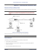
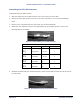

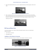


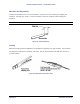
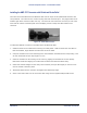
Table Of Contents
- Chapter 4. System Diagnostics and Operating Tips
- Appendix A. Initial Settings
- Appendix B. Installing the Configuration Software and Upgrading Firmware
- Appendix C. Technical Specifications
- Burst-Rate Limit
- Downlink/Uplink Throughput
- Frequency Plans
- Tx Power
- Antenna
- Receiver Sensitivity
- Maximum Distance Between Base Station and Subscriber Unit
- System
- Standards Compliance and Interfaces
- Configuration and Management
- Power/Environment Safety
- Physical Dimension
- Installation Details
- Optional Accessories
- Appendix D. Constructing Power and Ethernet Cables
- Appendix E. Lightning Protection Recommendations
- Appendix F. Technical Support and Training

Tsunami Multipoint Version 1.3 Installation Guide
7. Slide the threaded Woodhead cover over the completed assembly and loosely tighten it down to the
cable.
Figure 36. Woodhead Cover Placed Over RJ45 Connector
8. When connecting the cable to an SU, insert the RJ-45 connector into the SU’s Power and Ethernet
port until the locking tang clicks, slide the Woodhead body over the RJ-45 connector until it is seated,
tighten the coupling nut to seal the connector to the housing, and tighten the gland to seal the
assembly to the cable.
Figure 37. End Nut Seated on RJ45 Connector
BSU Power and Ethernet Cable
This section describes how to construct a Power and Ethernet cable for a BSU. This cable has the
following connectors:
▪ 18-pin Positronic connector
▪ 8-pin AMP connector
Installing an 18-Pin Positronic Connector
Perform the steps following the figure to install an 18-pin positronic connector on the cable.
Figure 38. 18-Pin Positronic Connector
Appendix D. Constructing Power and Ethernet Cables 65
CPN 63179 Issue Date: 01/24/03