
User's Manual Part 2
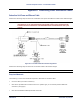
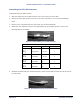

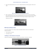


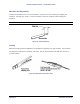
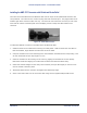
Table Of Contents
- Chapter 4. System Diagnostics and Operating Tips
- Appendix A. Initial Settings
- Appendix B. Installing the Configuration Software and Upgrading Firmware
- Appendix C. Technical Specifications
- Burst-Rate Limit
- Downlink/Uplink Throughput
- Frequency Plans
- Tx Power
- Antenna
- Receiver Sensitivity
- Maximum Distance Between Base Station and Subscriber Unit
- System
- Standards Compliance and Interfaces
- Configuration and Management
- Power/Environment Safety
- Physical Dimension
- Installation Details
- Optional Accessories
- Appendix D. Constructing Power and Ethernet Cables
- Appendix E. Lightning Protection Recommendations
- Appendix F. Technical Support and Training

Tsunami Multipoint Version 1.3 Installation Guide
Assembling the 8-Pin DIN Connector
To assemble the 8-pin DIN connector:
1. Slide the jacket of the 8-pin DIN connector over one end of the Cat 5 UV cable.
2. Prepare the Cat 5 cable ends by removing 0.75” of the main jacket. Do not cut the twisted pair
wires.
3. Remove 0.06” of insulation from the end of each wire in each twisted pair.
4. Solder each wire prepared in step 3 to the appropriate cup on the DIN connector. Refer to the
following table for information.
Figure 31. Soldered Wires on 8-Pin DIN Connector
Interface Cable Pin Assignments
DIN Pin Color Signal RJ45 Plug Pin
2
7
Orange
Orange/White
+24 VDC
- 24 VDC
4
5
6
8
Brown
Brown/White
+24 VDC
- 24 VDC
7
8
5
3
Green
Green/White
Tx+
Tx-
1
2
1
4
Violet
Violet/White
Tx+
Rx-
3
6
5. Assemble the metal shell over the DIN connector; make sure the DIN connector fits into the slots of
the metal shell.
Figure 32. Metal Shell Placed Over 8-Pin DIN Connector
Appendix D. Constructing Power and Ethernet Cables 63
CPN 63179 Issue Date: 01/24/03