
User's Manual Part 2
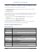

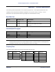
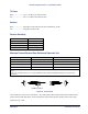

Table Of Contents
- Chapter 4. System Diagnostics and Operating Tips
- Appendix A. Initial Settings
- Appendix B. Installing the Configuration Software and Upgrading Firmware
- Appendix C. Technical Specifications
- Burst-Rate Limit
- Downlink/Uplink Throughput
- Frequency Plans
- Tx Power
- Antenna
- Receiver Sensitivity
- Maximum Distance Between Base Station and Subscriber Unit
- System
- Standards Compliance and Interfaces
- Configuration and Management
- Power/Environment Safety
- Physical Dimension
- Installation Details
- Optional Accessories
- Appendix D. Constructing Power and Ethernet Cables
- Appendix E. Lightning Protection Recommendations
- Appendix F. Technical Support and Training

Tsunami Multipoint Version 1.3 Installation Guide
Tx Power
BSU .....................+6 to +17 dBm (into antenna port)
SU.......................-48 to +15 dBm (into antenna port)
Antenna
BSU .....................Integrated, LHCP (left-hand circular polarization) 18 dBi
SU.......................Integrated, LHCP 21 dBi
Receiver Sensitivity
Burst Rate Threshold
60 Mbps -77 dBm
40 Mbps -81 dBm
30 Mbps -86 dBm
20 Mbps -89 dBm
Maximum Distance Between Base Station and Subscriber Unit
BURST-RATE CLOS
1
NLOS
2
60 Mbps 3 miles/5 km 1.2 miles/2 km
40 Mbps 4 miles/6.6 km 2 miles/3.5 km
30 Mbps 5 miles/8.3 km 2.4 Miles/4 km
20 Mbps 6 miles/10 km 3 miles/5 km
1
Clear-Line-of-Sight distance is calculated for 99.995% availability assuming no obstructions in the first Fresnel
Zone.
2
Near-Line-of-Sight distance is for a typical installation with moderate multipath/shadowing due to terrain and
structures.
Figure 29. Fresnel Zones
The Fresnel Zone refers to the radio beam. The radio signal’s path length and frequency determine the
Fresnel Zone’s width and shape. When a large part of the Fresnel Zone is blocked, some of the radio
signal’s energy is lost.
Appendix C. Technical Specifications 58
CPN 63179 Issue Date: 01/24/03