
User Manual Part 2


Lynx.GX Installation and Management
In the USA and Canada, this model radio can be installed with any gain directional antennas, as there is no
Effective Isotropic Radiated Power (EIRP) limit for the application of these systems for fixed point-to-point
applications. In other countries, EIRP limits may apply.
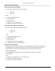
In the case of EIRP limits, use the lesser of either (P
out
- L
1
+ G
1
) or the EIRP limit within the previous equation.
You should check this equation in both directions to assure legal application.
An EIRP limit is the maximum RF energy that can be transmitted, as measured at the transmitting antenna, and
is usually determined by government regulations.
EQUIPMENT CO-LOCATION
When configuring radios in a hub or repeater configuration, perform careful engineering of the radio frequency
plans and antenna locations to minimize potential interference between the nearby radios.
As a rule of thumb, do not place opposite frequency plan radios (such as A1 and A2) at the same site. Using
alternate channels (such as A1 and A2) is highly unlikely to be successful (and therefore not recommended) due
to the high level of transmitter-to-receiver isolation required from the antenna system.
In most cases, you should use the same frequency plan (such as A1 and A1) or, in some cases, a different
frequency plan from the same side of the band (such as A1 and B1, when more than one channel plan is
available).
With careful engineering, you can easily place more than one radio of the same frequency channel plan at the
same site. When designing these configurations, antenna size, antenna polarization, and antenna location are
critical.
Antenna polarization always should be oriented such that adjacent links are oppositely polarized relative to one
another (that is, vertically and horizontally). This provides additional discrimination of the received signals
coming into the hub site. If you must place an odd number of links at the same location, ensure that the largest
angle is bounded by the two links of like polarization. Further interference analysis may be required to ensure
these adjacent links will provide adequate separation.
Changing polarization on the antenna system to the orientation that provides the maximum rejection to the
interference is also an extremely effective measure.
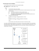
The radio must have access to a supply of appropriate power, either DC or AC (if the AC adapter option has
been ordered). The unit can be powered from a DC battery system, or from a solar or generator power plant,
usually with battery reserves. Typically, either a ± 24 or ± 48 volt supply is used.
For DC, be sure the cable is of sufficient gauge to carry the necessary current and is less than three meters
(9.75 feet) in length. A minimum gauge of 14 is recommended.
Before you install the radio, plan for the unit’s continuous power consumption needs. You also should plan for
backup power for critical communication circuits. Backup power lets the radios and associated equipment
operate continuously when primary power is interrupted.
The radio channel plans are shown in the Specifications document for your radio.
Appendix A. Installation Planning 52