
User Manual Part 2


Lynx.GX Installation and Management
Network Management System
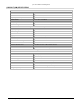
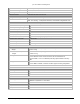
Connector RJ-45 (modular jack) 2 each
NMS 1 10/100 Base-Tx
NMS 2 10/100 Base-Tx
Test Point
RSL Voltage = -10mV per RSL (dBm); Range = 0.9 to 0.05 volts for –90 dBm to –5 dBm
GND Ground test point
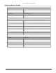
INTERFACE (RF UNIT)
Antenna Port
Connector Type-N female
Impedance 50 ohms
Signal See Unit Specifications for frequency channels
IF Port
Connector TNC female
Impedance 50 ohms
Signal Uplink: 749 MHz; Downlink: 140 MHz; +42 Vdc
Output RSL
Connector BNC female, cap and chain
Output Level
Voltage = -10mV per RSL (dBm); Range = 0.9 to 0.1 volts for –90 dBm to –10 dBm
500 Hz to 3 kHz for earphone jack
Audio Tone RSL and RSL earphone connectors are combined onto single connector
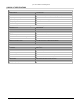
Temperature and Environment
Operating Temperature, RFU
-30° to +55° C
Operating Temperature, IDU
0° to +50° C
Humidity, IDU 95% max, non-condensing
Humidity, RF Unit 100%, all weather
Altitude Up to 15,000 ft. (5000 m)
Wind (RF unit) Up to 110 mph / 96 kts
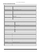
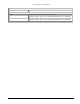
Fault and Configuration Management
Type
Integral SNMP Agent, Integral Web Server, Serial Craft Terminal CLI
Telnet, via 10/100BT
10/100 Base-Tx Ethernet port
(NMS1)
RJ-45 modular jack
Auto-negotiate speed and duplex; auto-MDI/MDI-X
10/100 Base-Tx Ethernet port
(NMS2)
RJ-45 modular jack
Auto-negotiate speed and duplex; auto-MDI./MDI-X
Configuration port VT-100 Craft Terminal; 9-pin D sub, female; 9600 baud
SNMP SNMP v2C, MIB II, Proxim Enterprise MIB
Network Element Managers HP OpenView or equivalent
SNMP Reports Alarm traps sent to up to 5 Managers; via MIB variables
Web Browser Compatibility IE version 5.0 or later (5.0, 5.5, 6.0); Netscape 7.0 or later
Appendix F. Lynx.GX Specifications 90