
User Manual Part 2


Lynx.GX Installation and Management
RFU RSL/TONE AND PIN ASSIGNMENT
The RFU (RF Unit) is provided with a BNC (Bayonet Neill Concelman) connector that provides a dual function
for assisting in antenna installation and alignment:
▪ Provide a high impedance drive DC voltage level corresponding with the RSL (Received Signal Strength). A
standard DVM (Digital Volt Meter) is used for this purpose.
▪ Provide a low impedance drive AC voltage tone that indicates the RSL. This tone is monitored using a 40
ohm headset. A higher pitch tone indicates a stronger signal.
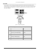
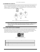
The following figure illustrates the BNC connector.
Figure 16. RSL/Tone BNC Female Panel Connector
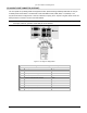
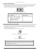
Figure 17. RSL/Tone BNC Male Connector to DVM or Headphone
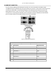
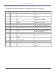
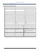
BNC Port Connector Pin Assignment Description
Pin Description
Center DVM mode:
Lower voltages for higher strength signals:
Received Signal Level: RSL (dBm) = -10mV per RSL
Examples: -70 dBm: 0.7 V
-50 dBm: 0.5 V
-30 dBm: 0.3 V
Earphone mode:
Higher pitch tones for higher strength signals:
BNC Audio: Tone Frequency (Hz) = 460800/(-2 * RSL (dBm) +76)
Examples: -70 dBm: 2133 Hz
-50 dBm: 2618 Hz
-30 dBm: 3388 Hz
Outer Common Signal/Chassis Ground
Appendix D Connectors and Pin Assignments 83