
User Manual Part 2


Lynx.GX Installation and Management
RSL AND GND CONNECTORS ON IDU
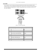
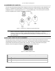
The RSL (Received Signal Level) and GND (Ground) front panel test points are both single connection female
test points that permit insertion of a 0.062” test probe pin from a VOM (Volt Ohm Meter). The test point is
located on the IDU just below the “Proxim” logo and the radio type on the unit.
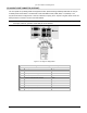
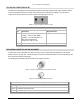
Figure 13. RSL and GND Connectors on IDU
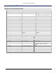
RSL and GND Connector Pin Assignment Description
Pin Description Signal Direction
RSL Received Signal Level (voltage), where
Voltage = -10mV per RSL (dBm)
Example: +0.5 volts indicates a -50
dBm received signal level.
Range from 0.9 to 0.1 Volts
Output
GND Common Signal/Chassis Ground
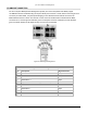
RFU/ANTENNA CONNECTOR AND PIN ASSIGNMENT
The RFU (RF Unit) is connected to the antenna using a 50 ohm coaxial cable terminated with male Type N
(Neill) connectors on each end. The female Type N connector provides termination for this coaxial cable on the
RFU enclosure and antenna assembly.
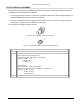
The following figure illustrates the RFU Antenna port Type N connector.
Figure 14. Antenna Type N Female Front Panel Connector
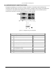
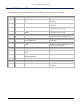
Figure 15. Antenna Type N Male Connector
TNC Port Connector Pin Assignment Description
Pin Description
Center Transmitter and Receiver RF
Outer Common Signal/Chassis Ground
Appendix D Connectors and Pin Assignments 82