
User Manual Part 2


Lynx.GX Installation and Management
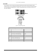
IDU NMS PORT CONNECTORS
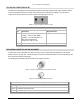
The two front panel NMS (Network Management System) Port connectors (NMS1 and NMS2) support
10/100BaseT Ethernet serial data using two 8-pin modular jack connectors. Shown below is the wiring for each
connector per USOC 568B. Two jacks permit bridging to other Ethernet devices without the need for an
additional Ethernet hub or switch. The left LED on each connector will illuminate to indicate that the NMS
connection is on, and the right LED indicates green for full duplex and off for half duplex (the LED will flash
green to indicate collisions in half duplex mode). The front view is illustrated.
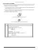
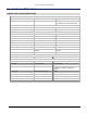
Figure 8. NMS Plug Pin Assignment
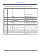
NMS Plug Connector Pin Assignment Description
Pin Description Signal Direction
1 NMS Data Out + Output
2 NMS Data Out - Output
3 NMS Data In + Input
4 * (connected to cross-talk suppression circuits)
5 *
6 NMS Data In - Input
7 *
8 *
Appendix D Connectors and Pin Assignments 78