
User Manual Part 2


Lynx.GX Installation and Management
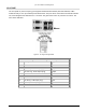
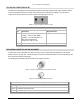
IDU AUX DATA PORT CONNECTOR (DCE PORT)
The front panel Aux (Auxiliary) Data Port supports EIA-561 (electrical wiring standard) serial data on an 8-pin
modular jack as shown below. The data rate is user selectable to 2400, 4800, 9600, or 19,200 bps. The
asynchronous data is configured for 1 start bit, 8 data bits, no parity, and 1 stop bit. The green LEDs on the Aux
Data port have no function. The front view is illustrated.
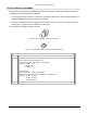
Note: Pins 2 and 7 are not used on the AUX DATA port of the radio. The user may connect a digital signal to
these pins; however, operation of this data port is not affected.
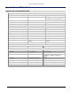
Figure 7. Aux Plug Pin Assignments
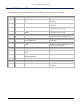
Aux Data Plug Connector Pin Assignment Description
Pin Description Signal Direction
1 NC: No Connection
2 +3.3 V (Data Set Ready)
3 +3.3 V (DTE)
4 Common Signal/Chassis Ground Gnd
5 Aux Data Out Output
6 Aux Data In Input
7 +3.3 V (Clear To Send)
8 +3.3 V (RTS)
Appendix D Connectors and Pin Assignments 77