
User Manual Part 2


Lynx.GX Installation and Management
Appendix D. Connectors and Pin Assignments
This section describes the radio port connectors and pin assignments for the IDU (Indoor Unit) and RFU (Radio
Frequency Unit).
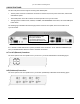
IDU MAIN TRAFFIC T1/E1 CONNECTORS
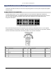
The main traffic ports for T1 or E1 connections appear on the front panel as multiple 8-pin modular jack
connectors wired per RJ-48C. The following figures show the actual format and layout of the T1/E1 connectors
(the 16T model is depicted), an illustration of the traffic port pin assignment, and a table listing the pin
assignment descriptions.
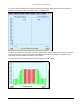
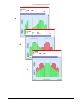
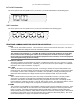
Figure 5. Port Connector Layout for 16 T1 Ports
Each connector has a green LED on the right side of the connector that illuminates when a T1 or E1 signal is
received at that port. The left LED is not used. The upper row has the connector tab in the up position, whereas
the lower row has the connector tab on the bottom position. The front view is illustrated.
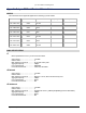
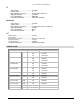
T1/E1 Port Connector Pin Assignment Description
Pin Description Signal Pin Description Signal
1 T1/E1 OUT-tip: Line transmit out (tip) Output 5 T1/E1 IN-ring: Line receive in (ring) Input
2
T1/E1 OUT-ring: Line transmit out
(ring)
Output 6 GND: Chassis Ground
3 GND: Chassis Ground 7 NC: No Connection
4 T1/E1 IN-tip: Line receive in (tip) Input 8 NC: No Connection
Appendix D Connectors and Pin Assignments 75