
User Manual Part 2


Lynx.GX Installation and Management
There are two external input alarms, independent of the relay outputs available. From the SysCfg page, you
can set whether an open or closed condition produces an alarm.
See the table of alarms in “Log Tab: Viewing Status and Alarms” on page 62. See “Connectors and Pin
Assignments” on page 46 for ALARM port connector information.
NMS1 and NMS2
There are two Ethernet 10/100 Base-TX connections (both switched) for access to the Network Management
System (NMS) using SNMP, HTTP, or Telnet. Both of these connections auto-negotiate speed and duplex,
and auto-sense MDI or MDI-X connections. On GX radios, the two 10/100BT ports are identical, and can be
used to daisy chain the NMS connections between units at a hub location or to connect to other local Ethernet
devices. See “Providing a Contiguous Management Link” on page 33.
AUX DATA
This is a serial interface port (RS-232) using an RJ-45 connector, supporting speeds from 2400 to 19200 baud
(set through the NMS). This allows auxiliary serial data connection from one end of the wireless link to the
other, completely separate and independent of the main bearer channel. It can be used for separate data
connections for serial devices. See “Connectors and Pin Assignments” on page 46 for AUX DATA port
connector information. Note that the aux data rate must be configured using the Web interface before use.
VF (Voice Frequency)
This RJ-45 connector is used to link two radios at a repeater site for Orderwire operation or to connect to an
external Orderwire system. This allows Orderwire calls to and from any point in the network that is connected.
The circuit is a 4-wire audio (2xTX and 2xRX) configuration. All phones off-hook hear and participate in the
call (behave as a ‘party line’). The NMS provides Orderwire addressing capability for individual radio terminal
signaling. See “Connectors and Pin Assignments” on page 46 for VF port connector information.
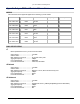
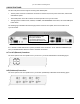
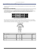
Front Panel LED Descriptions
Front Panel LEDs
LED Color Description
RF Link Green
Yellow
Red
Flashing Red
BER<10^-6
Bit errors occurring (when 10^-6 ≤ BER ≤ 10^-3)
Excessive bit errors or radio link failure (BER ≥ 10^-3 or sync loss)
Link Security ID mismatch within the last minute
RF Unit Green
Red
RF UNIT OK
RF UNIT alarm (Over-temp (>95°C), IDU to RFU communication failure, DC
power loss, or RFU detected hardware failure.)
Cable Green
Red
Cable between system board and RF UNIT is OK
Cable short longer than 5 seconds detected in the last minute
IDU Green
Yellow
Red
IDU OK
IDU warning (warning condition in IDU (over-temp or a fan failed)
IDU alarm (all fans failed or over-temp (>65°C)
DATA INPUT
(listed by
priority)
Red
Yellow
Green
Off
Input Alarm enabled; data not present on at least one enabled channel
Input Alarm disabled; data present on at least one channel
Input Alarm enabled; data present on all enabled channels
Input Alarm disabled; data not present on any channels
AIS OUT Off
Yellow
Not injecting AIS (Alarm Indication Signal, or all ones) in data stream
Injecting AIS in data stream
NMS Green
Off
Tx or Rx NMS data present on the interface
No NMS interface connection detected or no data present
LOOPBACK Flashing Yellow
Solid Yellow
Off
At least one data channel in loopback
Internal loopback is on and has detected at least one error
No loopbacks on any channels
Appendix C. Lynx.GX Front Panel and Connections 73