
User Manual Part 2


Lynx.GX Installation and Management
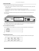
8xT1 or 8xE1 Connections
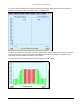
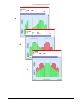
The center portion of the front panel for the Lynx.GX 8T / Lynx.GX 8E is illustrated in the following figure.
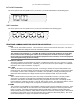
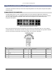
16xT1 Connections
The center portion of the front panel for the Lynx.GX 16T is illustrated in the following figure.
FRONT PANEL COMMON CONNECTORS, INDICATORS AND CONTROLS
To RFU
This is an RF TNC female connector. This connector is used to connect the IDU to the RFU. The center
conductor contains DC voltage as well as IF and telemetry signals.
WARNING!
The voltage on this connector is ~+ 42 VDC. Be careful not to short this conductor pin to the body
of the connector when installing the cable to the unit if DC power has been turned on or applied.
Do not under any circumstances connect RF test equipment to this connector as the test equipment
will be damaged instantly by this DC voltage.
± 24 VDC OR ±48 VDC
The power receptacle recommendation for positive or negative DC power is 24 or 48. However, it accepts
any voltage between 20 and 63 Volts. Optionally, you can use an AC-to-DC power adapter. For additional
information, see “Power Connections” on page 27.
RSL / GND
These are the radio’s two front panel test points. Connecting a voltmeter across the GND and RSL front
panel test points, the voltage reading corresponds to the Received Signal Level (RSL) of the near-end radio.
For example, a value of .65V corresponds to –65 dBm (-10mV per dBm). Pressing and holding the FAR
END button while measuring the voltage at these test points displays the RSL of the far-end radio.
CONFIG
This is a serial interface port (RS-232) to the radio using a Female DB-9 connector. This port provides
connection to a computer or terminal using a standard null-modem cable for retrieving diagnostic
information, and allows IP and SNMP Community String configuration for the radio. The settings for this
port are 9600 bps, 8 data bits, No Parity, 1 Stop Bit, and No Flow Control. The terminal emulation is VT100.
See “Connectors and Pin Assignments” on page 46 for CONFIG port connector information.
ALARMS
This connector provides alarms for external alarm collection systems using a female DB-9 connector. There
are two Form C relays that can be connected to other transmission equipment for monitoring alarm status
locally or remotely. One alarm represents Major alarms (usually alarm conditions) and the other Minor
alarms (usually warning conditions). Major Alarms correspond to red LEDs on the front panel. Minor alarms
correspond to yellow LEDs on the front panel (AIS Out does not affect the Minor Relay Alarm). See “Front
Panel LED Descriptions” on page 73 for specific LED descriptions.
Appendix C. Lynx.GX Front Panel and Connections 72