
User Manual Part 2


Lynx.GX Installation and Management
LYNX.GX FRONT PANEL
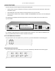
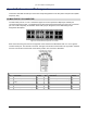
The IDU front panel can be thought of as having three distinct parts.
▪ The left portion of the IDU contains the connection for the RF Unit, the DC power connection, and the RSL
and GND test points.
▪ The middle portion of the IDU contains connectors specific to the Lynx.GX model.
▪ The right portion contains LEDs, CONFIG, ALARMS, and ORDERWIRE connections, and a FAR END push
button switch.
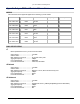
The following figure illustrates the left and right portions of the IDU front panel, which are the same for all
Lynx.GX models.
A T1 channel is a data channel for T1 (DSX-1) interface voice connection. An E1 channel is a balanced (120
ohm) or unbalanced data channel for CEPT-1 interface connections.
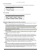
This center portion of the
front panel contains
connections specific to the
type and model of each radio.
4xT1 or 4xE1 (Balanced) Connections
The center portion of the front panel for the Lynx.GX 4T / Lynx.GX 4E is illustrated in the following figure.
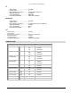
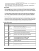
4xE1 (Unbalanced) Connections
The center portion of the front panel for the Lynx.GX 4E1 (unbalanced) is illustrated in the following figure.
Appendix C. Lynx.GX Front Panel and Connections 71