
User Manual Part 2


Lynx.GX Installation and Management
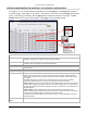
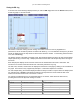
ALARMS TAB—MONITORING LINK STATUS
Click the Alarms tab to monitor both near-end and far-end link alarm status. Field descriptions follow the
figures. Note that the orientation of the alarms matches the position of the connectors on the front panel.
These alarms contain some more specific detail than the Front Panel display, and are helpful in determining
possible problems.
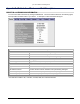
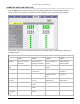
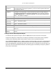
Alarms Window Field Descriptions
If Grey: If Green: If Yellow: If Red:
T1 Input or
E1 Input
Input Alarm is Disabled
and T1 or E1 Input is
not present
T1 or E1 Input is
present and T1/E1
Input Alarm is enabled.
Input Alarm is Disabled
and T1 or E1 Input is
present
T1 or E1 Input is NOT
present and Input
Alarm is enabled.
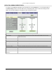
T1 or E1
AIS
NOT injecting all 1s. N/A Injecting all 1s in data
stream.
N/A
Radio Sync
N/A Radio link is
synchronized.
N/A Radio link is NOT
established.
Bit Error
N/A Error-free operation. Bit Error Rate is
between 10e-6 and
10e-3
Bit Error Rate is worse
than 10e-3.
Fan
Summary
N/A Fans are operating
correctly.
One or two fans are
malfunctioning.
Two or three fans are
malfunctioning.
Major Relay
N/A No Major Alarm
present
N/A Major Alarm exists
Minor Relay
N/A No Minor Alarm
present
Minor Alarm exists N/A
External
Input Alarm
1 or 2
N/A No External Alarm
present
N/A External Alarm exists
Appendix B. Web Interface Windows and Field Descriptions 61