
User Manual Part 2


Lynx.GX Installation and Management
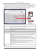
After entering any configuration changes, click on the Apply button. The Default button installs the default
settings for all entries but does not apply them until the Apply button is clicked. Any changes outside the range
of acceptable values is identified for the user (with a “Failed to change configuration(s)” message) and the
changes fail to apply.
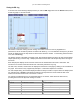
SYSTEM CONFIGURATION TAB—CONFIGURING TX POWER, SECURITY LINK ID, AND TX CHANNEL PLAN
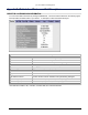
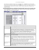
Select the Sys Cfg tab to configure transmitter power, orderwire, security, aux port speed, and RF frequency
settings. Make one change at a time and click Set.
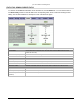
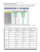
Sys Cfg Window Field Descriptions
Tx Power (dBm)
Power setting range in dBm. Choose from +5 to +25 dBm, in 1 dB steps.
Orderwire Address
The Orderwire telephone address. Choose any 2-digit number from 00 to 99.
Link Security Code Security code set by the user; choose 12 characters using an alphanumeric
combination of 0 to 9 and a to f (hexadecimal). This code must match the far end
radio to establish the wireless link. Changing the code initiates a 60-second timer for
the radio to check and verify the code; the RF link LED will flash red for 60 seconds
after the LINK ID is matched. Provides 12
16
possible codes (281 trillion).
Note: All user data traffic is invalid until the link security code is matched and the LED
stops flashing.
Aux Port Speed
(bps)
Speed of the auxiliary port in bits per second, in the range of 2.4 kbps to 19.2 kbps.
Must match far end radio.
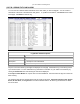
RF Frequency
(TX/RX in GHz)
You can select the transmit/receive channel pair in this field. Depending upon the
model of the radio, the available choices are listed on the pull down menu. See
Technical Specifications on page 69 for information specific to the individual radio
models.
Depending upon the High or Low model of the RFU, the frequency plans listed here
show the transmit frequency on the Low half of the 5.8 GHz band, or the High half of
the 5.8 GHz band. High and low frequencies cannot be mixed.
Note: Each side of the link must have opposite Tx/Rx values.
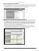
External Input
Alarm 1 / 2
The external alarm inputs can be set to cause an alarm under an open or closed
condition between the appropriate pins on the front panel interface. These fields lets
you set the state that is to activate the alarm for external input alarms 1 and 2.
Closed is when the input is connected to GND. Open is when the input is not
connected to GND.
Appendix B. Web Interface Windows and Field Descriptions 58