
User Manual Part 2


Lynx.GX Installation and Management
INTERFACE CONFIGURATION TAB—MODIFYING T1/E1 INTERFACE CONFIGURATIONS
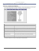
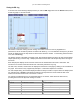
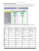
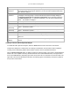
To modify the T1 or E1 channel interface configurations, click the Intf Cfg tab. The Intf Cfg page is shown in
the following figure, which depicts a Lynx.GX 8T. A description of each column in the Intf Cfg page follows the
figures. After making your changes, click the Apply button to implement and save your changes. The Get
Defaults button lets you see the default settings. Click Apply to save the default settings.
Intf Cfg Window Field Descriptions
Input Alarm Enable
Lets you enable or disable the Input Alarm of individual T1/E1 channels. Disabled alarms are not
reported on the alarm log. Unused channels should be disabled.
AIS Enable
Lets you enable or disable the automatic injection of AIS into the T1/E1 data stream during RF
Link failure. This is relevant only if the channel is enabled.
Line Buildout
T1 interface line length setting for each channel. A drop-down menu provides selections from
zero to 655 feet.
Line Code
AMI/B8ZS line code setting for each T1 interface.
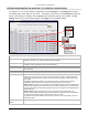
Loopback Config
Activates or deactivates one of three loopback modes at the T1/E1 input port. Only one
loopback can be running from one port on each side of the link at a time. Setting a loopback
while another loopback is running stops the previously running loopback and starts the recently
set loopback.
Local LB: Local radio line interface is in loopback to the line connector (does not test the
wireless link). Data that enters the connector is looped back at the local connector.
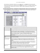
Remote LB-int: The far end or remote radio is set to loopback data so that the received signal is
sent back to the originating local radio from the far-end radio’s interface port. The radio uses an
internally generated signal and external signals are ignored. This tests the entire wireless link for
the selected input.
Remote LB-ext: Similar to Remote LB-int, but an external signal is required locally. The
externally injected signal passes through the entire radio link, is looped at the far end’s interface
port and is sent back across the link, returning to the input connector.
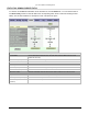
Any channel set to loopback takes that channel out of service. The loopback LED on the front
panel blinks yellow.
Far-End Loopback
Status
Displays the status of loopbacks initiated at the far end radio.
Appendix B. Web Interface Windows and Field Descriptions 57