
User's Manual


INSTALLATION AND MAINTENANCE MANUAL
LYNX.sc E1 FAMILY
SPREAD SPECTRUM RADIOS
SEPTEMBER 1999
PAGE 3-48 SECTION 3: INSTALLATION & ADJUSTMENTS
3.14.3 Diagnostics Port Operation
The Diagnostics Port is used to retrieve diagnostic or network management information about the
LYNX.sc radios by means of a computer connection. This can be accomplished locally or remotely.
Remote diagnostic port connections require either a modem (not included) connection be made to
the serial port, when a local dial-up phone line is available at a radio site, or by means of direct
connection through the AUX DATA port (Service Channel). The use of the AUX DATA channel can
provide a “network management” port where serial interface data is available from all LYNX.sc radios
in a network, provided that they are configured properly for this type of operation. (This section and
Section 3.14.4 describe this further).
The diagnostics port allows connection of either EIA standard RS-232 or RS-422 devices to poll and
receive status of the LYNX.sc radio. This serial port provides similar information to that which is
normally available to a local operator by means of visual alarms and status (front panel LEDs,
ADDRESS, DIP switch settings etc.), including voltage level measurements (such as RSL, PWR)
and alarm port (see Section 3.14.2) status. The diagnostics port can also provide extended
information including some advanced diagnostics and configuration information. Any information that
is available on the far-end terminal is also available at the near-end Diagnostics port (such as far-
end RSL, far-end alarms) by means of bridging the AUX DATA port (as described in Section 3.14.4).
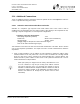
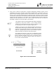
A DIP switch is used to define the command protocol for this port as shown in Figure 3-22. The
default setting is for TBOS commands (as described later in this section). The other setting is for
factory use only.
Figure 3-22: Diagnostic Port Protocol Selection
SW1