
User's Manual


INSTALLATION AND MAINTENANCE MANUAL
LYNX.sc E1 FAMILY
SPREAD SPECTRUM RADIOS
SEPTEMBER 1999
SECTION 3: INSTALLATION & ADJUSTMENTS PAGE 3-47
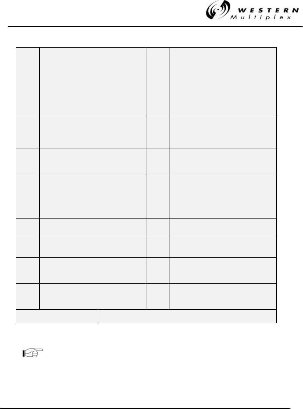
PIN 2 DATA LOSS (1 or 1&2) - in alarm if no
incoming data is received into the transmitter
for channel 1 (for the 4xE1 model, includes
channel 2). Data Loss is activated when the
input signal drops below 0.97 volts for 175 bit
intervals and is deactivated as soon as the
input signal level rises above 0.97 volts. Radio
transmits AIS to the far-end if in alarm. This
alarm may be disabled by DIP switch selection
(see Section 3.12.4).
PIN 16 NC, SUMMARY ALARM, FORM C - normally
closed connection on summary alarm relay.
PIN 4 DATA LOSS (2 or 3&4) – use essentially the
same description as Data Loss (1 or 1&2), for
channel 2 (for the 4xE1 model, channels 3&4).
PIN 17 NO, OUT OF SERVICE SUMMARY ALARM,
FORM C - normally open connection on out-of-
service summary alarm relay. Closed when in
alarm.
PIN 6 BER - in alarm when the received signal is
degraded to an error rate above radio threshold
(approximately 1 x 10
-6
)
PIN 18 C, OUT OF SERVICE SUMMARY ALARM,
FORM C - common connection for the out-of-
service summary alarm relay.
PIN 8 AIS OUT - in alarm when the BER exceeds 1 x
10
-3
for the received signal, or when there is an
RX SYNC alarm condition. Near-end radio
CEPT-1 line output has AIS when in alarm. This
alarm may be disabled as described in Section
3.12.5.
PIN 19 NC, OUT OF SERVICE SUMMARY ALARM,
FORM C - normally closed connection on out-
of-service summary alarm relay. Open when in
alarm.
PIN 10 FAN - in alarm when one or both of the internal
fans are not operative.
PIN 21 NOT USED
PIN 12 FAR-END - in alarm when the far-end radio has
an alarm condition.
PIN 22 NOT USED
PIN 14 NO, SUMMARY ALARM, FORM C - normally
open connection on summary alarm relay.
Closed when in alarm.
PIN 24 TX PWR MON - voltage equal to the TX PWR
front panel voltage.
PIN 15 C, SUMMARY ALARM, FORM C - common
connection on the summary alarm relay.
PIN 25 RSL MON - voltage equal to the RSL front
panel voltage. Equals far-end RSL if DISPLAY
FAR END button is pressed and held.
PINS 1, 3, 5, 7, 9, 11, 20, & 23 GROUND, CHASSIS CONNECTION
Table 3-E: Alarm Interface Connections
All alarms are active for a minimum of one second, or as long
as the alarm condition persists, which ever is longer.
TTL signals are “in alarm” when there is a TTL zero condition
(0 V to ± 0.5 V).