
User's Manual


INSTALLATION AND MAINTENANCE MANUAL
LYNX.sc E1 FAMILY
SPREAD SPECTRUM RADIOS
SEPTEMBER 1999
PAGE 3-46 SECTION 3: INSTALLATION & ADJUSTMENTS
3.14.2 Alarm Connections
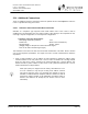
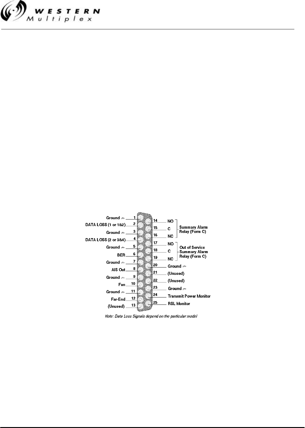
External alarm outputs are provided at the 25-pin, D-type subminiature ALARM connector. There are
two Form C summary alarm relays capable of switching 30 VDC at 1 A. Also, individual alarm logic
outputs capable of sourcing and sinking 1mA are provided. These individual alarms interface to a
single standard TTL load. When the unit is IN ALARM = “0”, the TTL output is 0 V to ±0.5 V. When
the unit is NO ALARM = “1”, the TTL output is +3.5 V to +5.5 V. See Table 3-E and Figure 3-21 for
Alarm Connections.
The “summary” alarm (Form C relay) is activated by any near-end front panel LED alarm condition,
including if the loopback mode is enabled.
The “out-of-service summary” alarm (Form C relay) is activated by any of the following alarm
conditions:
v RX SYNC
v Radio Fail
v Loopback Enabled
Figure 3-21: Pin Connections, ALARM Interface