
User's Manual


INSTALLATION AND MAINTENANCE MANUAL
LYNX.sc E1 FAMILY
SPREAD SPECTRUM RADIOS
SEPTEMBER 1999
SECTION 3: INSTALLATION & ADJUSTMENTS PAGE 3-45
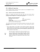
4. If the LYNX.sc radios are connected in a repeater configuration, Orderwire services can be
established to all LYNX.sc terminals in the network by implementing a connection of their rear-
panel connectors between repeater terminals. At the repeater site, a cable can be connected to
the two LYNX.sc terminals between their rear panel VF 25-pin connectors as shown in Figure
3-20. With this cable in place, the Orderwire function will operate at terminals at each end of the
repeater and at the repeater site. This function can be continued through several repeater sites
if desired. For hub connections of 3 or more LYNX.sc radios at the same site, an external 4-
wire bridge is required to connect all radios to the orderwire.
The orderwire system can be integrated with orderwire equipment
supported by many other vendors. If your existing orderwire
network uses 2 digit addressing, and 0 dBm VF interface, it can
be connected to a LYNX.sc as shown in Figure 3-20.
Dialing a V (star key) on the orderwire telephone implements an
“all call” feature which rings all connected radios. Also, if a phone
anywhere in the connected network has accidentally been left off-
hook, the # (pound key) key can be used to mute all off-hook
handsets until they are placed on and off hook again.
The orderwire operates like a “party line”. All telephones provide
communication to all other telephones in the connected network.
Even if a particular telephone does not ring, it can still be used to
talk and listen to any ongoing orderwire activity if the orderwire is
in use at other terminal locations.
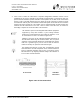
Figure 3-20: VF Port Connection
VF Connector
OrderWire
Connection