
User's Manual


INSTALLATION AND MAINTENANCE MANUAL
LYNX.sc E1 FAMILY
SPREAD SPECTRUM RADIOS
SEPTEMBER 1999
PAGE 3-26 SECTION 3: INSTALLATION & ADJUSTMENTS
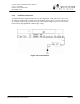
3.12 DIP Switch Settings
A quick reference guide to all DIP switches is provided in Appendix B.
DIP switch settings are noted by their position, either up (1), or down (0),
not by on/off as may be printed on the DIP switch assembly.
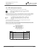
3.12.1 Channel Selection
The LYNX.sc radio offers several frequencies of operation except for the 2.4 GHz 2xT1 and the 5.8
GHz 4xT1 models (see Section 3.5).There are DIP switch segments (typical numbers 5 through 8
on SW3) which define the frequency channel plan of the LYNX.sc radio (refer to Appendix B). The
DIP switches must be set to match the filter assembly that is mounted on the radio. For single and
double capacity models, positions 5,6 and 7 define the frequency channel plan of the radio (e.g. A,
B, C), the last DIP switch defines the transmit channel of the radio (e.g. A1 or A2).
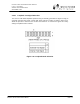
Radios are shipped from the factory with their DIP switch segments set to match the installed filter.
In most cases, no modification of these switches is required.` Also, there are labels on the RF filter
illustrating the correct DIP switch settings. One label is right side up and the other is upside down.
Set the DIP switch settings for the label that is right side up. If a new filter is installed, or the
existing filter is rotated for opposite channel configuration (e.g. A1 to A2), reset the DIP switches to
match the right side up label on the filter. Refer to Section 4.2 for more information.
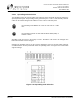
The radio channel selection is user adjustable by removing and replacing, or reversing the filter
assembly. This allows units of the same radio model to be used as spares for several channels. For
example, if a network of LYNX.sc radios has several radios using all three E1 channel plans at 5.8
GHz, a single spare unit of any channel plan can be used to spare all the radios. If a radio failure
were to occur in the network, the filter assembly of the failed unit would be removed and replace the
filter assembly in the spare radio. The DIP switch segments on the spare may need to change to
match the installed filter and the spare radio could be put into service.
The DIP switch setting must match the filter assembly mounted on the
radio. Also, both radios of a link must have opposite channel plans (e.g.
A1 and A2).
Consult Section 4.2 of this manual for more information on changing RF
channels. Consult Appendix B for proper frequency channel switch
settings.
Other NON-standard frequency plans may be offered in the future. In
these cases, follow the DIP switch setting on the filter label.