
User's Manual


INSTALLATION AND MAINTENANCE MANUAL
LYNX.sc E1 FAMILY
SPREAD SPECTRUM RADIOS
SEPTEMBER 1999
SECTION 3: INSTALLATION & ADJUSTMENTS PAGE 3-25
3.11 CEPT-1 (E1) InterfaceConnection
The CEPT-1 interface connection to the LYNX.sc radio is on the rear panel.
Additional external lightning protection devices are recommended
for the CEPT-1 connections if the radio is installed in an area
prone to lightning.
The CEPT-1 connection to the LYNX.sc is at the data interface on the rear of the shelf. Individual
BNC connectors are used to interface the line transmit and receive functions. Seventy-five (75) ohm
co-axial cables with BNC fittings should be used to connect LYNX.sc to external equipment.
If a balanced 120 ohm connection (RJ45) is required, an
optional balun will provide this interface. If you can not locate
these baluns (balanced/unbalanced) devices, please consult
the factory.
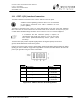
The DATA OUT port provides a bipolar signal (positive and negative pulses) referenced to
ground, with the BNC shield connected to ground.
However, the DATA IN port accepts a similar bipolar signal with the BNC shield normally left OPEN
(floating) in order to eliminate any ground loop problems. If desired, the BNC shield on the DATA IN
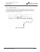
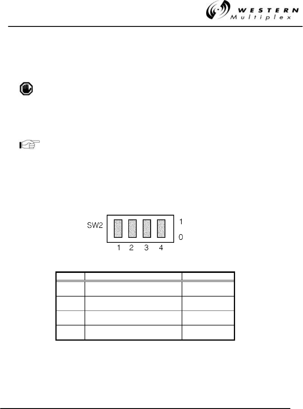
port may be grounded using the selector switch SW2.
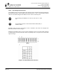
Position Description Setting
1 Grounding Condition Channel 1 0 = Floating
1 = Grounded
2 Grounding Condition Channel 2* 0 = Floating
1 = Grounded
3 Grounding Condition Channel 3* 0 = Floating
1 = Grounded
4 Grounding Condition Channel 4* 0 = Floating
1 = Grounded
* Where applicable
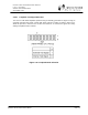
Figure 3-11: CEPT-1 Interface Grounding Switch