
User's Manual


INSTALLATION AND MAINTENANCE MANUAL
LYNX.sc E1 FAMILY
SPREAD SPECTRUM RADIOS
SEPTEMBER 1999
SECTION 3: INSTALLATION & ADJUSTMENTS PAGE 3-23
To coarse align the antenna, first set it for flat elevation (no up or down tilt) using a spirit level. Then
point it at a heading marker obtained using a compass back-bearing from an adjacent location,
(ideally, 100 feet or more away from the antenna).
If a heading marker cannot be set sufficiently far away (for example when on a city building roof or
looking through a window) then a rough azimuth setting can be obtained by sighting along the
antenna feed.
It should be verified that both antennas are on the same
polarization by using the manufacturer’s instructions. Otherwise
the RSL will be approximately 25 to 30 dB below the calculated
level.
Most antennas will also need fine alignment obtained using an operating link because it is very
important to maximize the receive RF signal level at each end of the radio link.
Read Section 3.7 before applying DC power to the LYNX.sc radio.
Once the coarse alignment has been set-up at both ends, then the link can be powered and some
level of reliable communication established. The voltage at the LYNX.sc front panel RSL test point
should be measured with a DVM to determine the relative receive RF signal level.
For the fine alignment, adjusting first the azimuth and then the elevation of the local antenna will
maximize the RSL voltage. Then, the far antenna is aligned in the same way, using the RSL voltage
of its local LYNX.sc radio.
When aligning antennas it may be convenient to run two wires from the RSL and ground test points
to the antenna so that the voltmeter reading is directly visible to the technicians aligning the
antenna. Also, a cellular telephone or two-way radio may be useful for coordinating alignment
activities between both ends of the link. Once the radios are coarse aligned and synchronized, the
built-in orderwire phone service can also be used to coordinate alignment between both ends of the
link.
An orderwire telephone will provide end-to-end voice communications
once radios are synchronized. Synchronization usually can be
accomplished by coarse alignment only. After synchronization, the
orderwire phones can be used to communicate between radio sites for
antenna fine alignment. The phone interconnect cable can be
extended to the antenna when desired.
The larger the antenna size, the more critical alignment becomes: for example, with a 2 foot dish,
the antenna can be moved ±3 degrees off the correct heading before the receive signal level drops
by 3 dB. This compares with a 6-foot dish which may only be moved ±1 degree for the same
degradation.
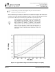
The graph shown in Figure 3-10 shows the typical variation of RSL voltage as the receive signal level
is increased from threshold to a higher level. There is some variation between LYNX.sc receivers,
but an approximate estimate of the potential RSL value may be made using this figure.