
User's Manual


INSTALLATION AND MAINTENANCE MANUAL
LYNX.sc E1 FAMILY
SPREAD SPECTRUM RADIOS
SEPTEMBER 1999
PAGE 3-16 SECTION 3: INSTALLATION & ADJUSTMENTS
3.7 Power Connection and Wiring
There is no ON/OFF switch on the LYNX.sc. As soon as
power is applied, the equipment will be operational. This
means that there can be up to 1W of RF power present at
the antenna port. The antenna port should be terminated
before power is applied.
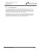
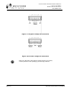
Power is connected using the DC power plug contained in the Accessory Kit. Use Table 3-A or 3-B
along with the associated diagram of Figure 3-7 or 3-8 to connect the DC power cables. For
example, for a negative DC power input, use Table 3-A and Figure 3-7.
NEGATIVE DC POWER INPUT
(–20 TO –63 VDC)
PIN FUNCTION
1 Power (–DC)
2 Ground (see figure 3-7)
3 Return (+DC)
4 Return (+DC)
5 Ground (see figure 3-7)
6 Power (–DC)
Table 3-A: DC Power Connection for Negative Supply
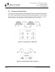
POSITIVE DC POWER INPUT
(+20 TO +63 VDC)
PIN FUNCTION
1 Return (–DC)
2 Ground (see figure 3-8)
3 Power (+DC)
4 Power (+DC)
5 Ground (see figure 3-8)
6 Return (–DC)
Table 3-B: DC Power Connection for Negative Supply
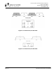
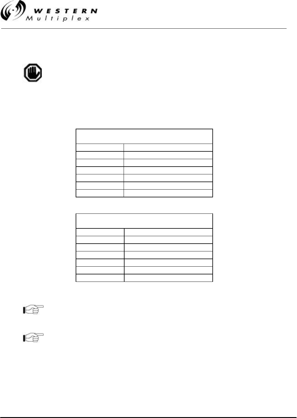
Pins 1 and 6 are connected together on the motherboard. Either
pin may be used to apply (-DC) DC power input. Similarly, pins 3
and 4 are connected together on the motherboard and may be
used to apply (+DC) DC power input.
For DC power return connection, connect to the opposite voltage
(either the -DC or the +DC Pin) and connect the return to ground
at the DC power plug on pins 2 and/or 5.